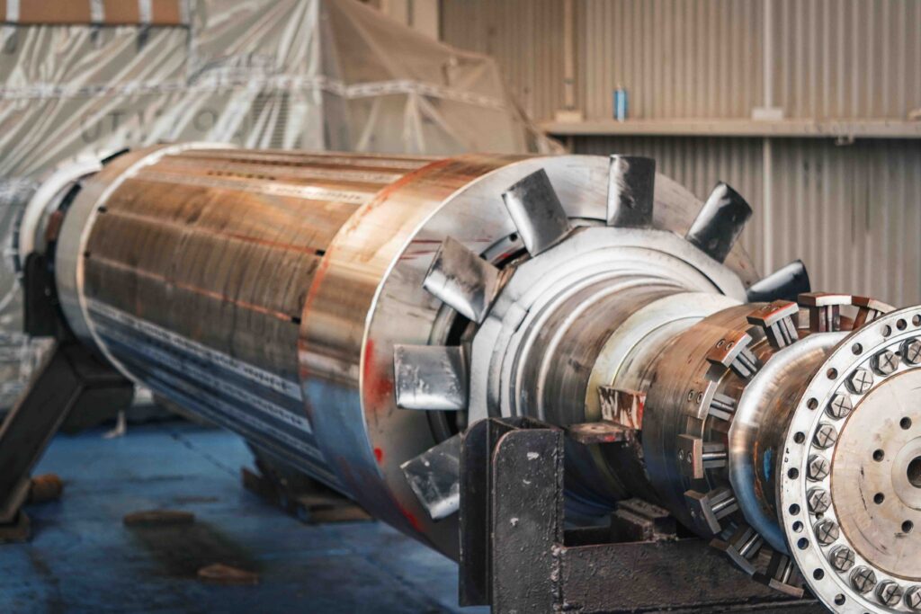
A paper mill drive system is the combination of motors, gearboxes, couplings, and control equipment that moves and regulates every rotating element in the papermaking process. Because paper is formed, pressed, dried, and wound as a continuous web, every section of the machine must turn at a coordinated speed relative to the others, and drive systems in paper mills exist to maintain that coordination without interruption.
Unlike batch manufacturing, a paper machine cannot simply stop and restart without risk to the sheet. Coordinated mechanical and electrical drive control keeps tension, speed, and torque within limits that the web can tolerate, section after section, for the full length of a production run.
How Paper Mill Drive Systems Work
Role of Drive Systems in Paper Production
Each rotating component on a paper machine, from pulpers to rewinders, depends on a drive system to convert electrical energy into controlled mechanical motion. The drive system determines how quickly a roll accelerates, how firmly it holds speed under load, and how it responds when conditions change, such as a grade change or a sheet break.
Sectional Drives and Line Shaft Systems
Older paper machines relied on a single line shaft that mechanically linked multiple rolls together, so all sections turned at speeds fixed by gear ratios along that shaft. Sectional drive systems replace this with individually motorized sections, each controlled electronically, which allows small speed differences between sections to be introduced deliberately rather than fixed mechanically. This flexibility is central to modern paper machine drive systems, since draw and tension requirements differ from one section to the next.
Master and Follower Drive Control
In a sectional arrangement, one section is typically designated as the master reference, and the remaining sections follow it as a percentage of that reference speed. This master and follower structure keeps the entire machine synchronized while still permitting controlled speed offsets between adjacent sections, which is necessary to manage draw and shrinkage as the web moves from wet to dry areas of the machine.
Main Components of Paper Mill Drive Systems
Electric Motors
Paper mill motors supply the rotational force needed to turn rolls, refiners, pumps, and reels. In paper machine applications, motor selection depends on the torque needed at startup, the torque needed to hold speed under continuous load, and how the motor behaves during acceleration and deceleration, since these are different operating conditions from simple constant-speed running.
Variable Frequency Drives
A variable frequency drive regulates motor speed and torque by adjusting the frequency and voltage supplied to the motor. In paper mills, VFD control allows each sectional motor to follow its speed reference precisely, respond to load changes, and execute controlled acceleration or deceleration rather than abrupt speed changes that could stress the web or the mechanical drivetrain.
Gearboxes and Speed Reducers
A gearbox changes rotational speed and torque through a set of gears, and its ratio is selected according to the speed and torque demands of the driven equipment. A speed reducer specifically lowers the output speed from the motor while increasing the available torque, which is often required because motors run efficiently at higher speeds than many paper machine rolls actually need. These two functions overlap but are not identical, and selecting one without considering the other can leave a drive undersized or oversized for its load.
Couplings Shafts and Encoders
Couplings transmit rotational motion between the motor, gearbox, and driven roll while accommodating minor misalignment and absorbing some torsional shock. Shafts carry that motion along the drivetrain, and their alignment directly affects vibration and bearing life. Encoders attached to motors or rolls provide speed and position feedback, which is the information that closed-loop drive control depends on to hold accurate speed and synchronization.
Control Cabinets and Communication Systems
Control cabinets house the VFDs, protective devices, and control logic for one or more drive sections, and they must be suited to the mill environment in terms of cooling and enclosure protection. Communication networks link these cabinets to a central control system, carrying speed references, feedback signals, and fault information between sections so that master and follower coordination functions as intended across the whole machine.
Drive Systems Across Paper Mill Sections
Stock Preparation Equipment Drives
Pulpers, agitators, pumps, and refiners often present different starting conditions from the rest of the machine, since they may need to move a dense or viscous stock from standstill, producing high starting torque demands even though running speed itself may be relatively stable. Motor and gearbox selection in this area focuses more on torque capability during startup and varying load than on precise speed synchronization with the paper machine itself.
Forming and Press Section Drives
In a crescent former tissue machine, forming and press section rolls handle a wet, fragile web, so their drives must maintain accurate relative speeds to avoid stretching, compressing, or breaking the sheet. Load conditions are steadier than in stock preparation, but the tolerance for speed error is much smaller because the web has very little strength at this stage.
Dryer Section Group Drives
Dryer sections typically use grouped drives, where multiple cylinders are coordinated as a single controlled group rather than driven individually. As the web loses moisture and shrinks through the dryer section, small speed differences between drying groups are required to manage this shrinkage without introducing excess tension or slack.
Calender Reel Slitter and Rewinder Drives
Calenders, reels, slitters, and rewinders operate on a web that has full strength but is sensitive to tension changes that affect finish quality or roll structure. Reel and rewinder drives in particular must adjust torque continuously as roll diameter increases, which distinguishes them from upstream sections where roll diameter is fixed.
Speed Draw and Tension Control
Paper Machine Speed Synchronization
Paper machine sections are coordinated to a common reference speed, but they are rarely set to run at identical surface speeds throughout the machine. Deliberate speed differences, known as draw, are introduced between sections to manage the natural shrinkage and tension changes that occur as the sheet moves from a wet state to a dry, finished state.
Encoder Feedback and Closed-Loop Control
Closed-loop drive control compares the actual speed reported by an encoder against the commanded speed reference and adjusts motor output accordingly. This feedback loop is what allows sectional drives to hold precise speed under changing load, rather than relying on an open, uncorrected speed command that could drift under real operating conditions.
Draw Control and Web Break Prevention
Draw control sets and maintains the small speed offsets between sections that keep web tension within an acceptable range. When draw settings are incorrect or when sections fail to respond consistently to their speed references, the web may experience uneven tension that increases the likelihood of wrinkles or sheet breaks.
Winding Tension and Diameter Compensation
As a reel or rewinder builds diameter, the torque required to maintain constant web tension changes even if rotational speed stays the same, since tension depends on the relationship between torque and roll radius. Diameter compensation and taper tension strategies adjust torque as the roll builds, generally reducing tension gradually toward the outer layers to avoid overly tight or overly loose winding, without requiring a single fixed numerical setting across different products.
How to Select a Paper Mill Drive System
Motor Power Speed and Torque Requirements
Selecting a drive begins with understanding the torque and speed demands of the specific driven equipment, including the difference between starting torque and running torque. Motor power alone is not sufficient for selecting a complete drive system, since two applications with similar power ratings can have very different torque and speed profiles.
VFD Control Modes
Variable frequency drives can be configured for different control modes depending on whether the application prioritizes precise speed regulation, torque regulation, or a combination tied to closed-loop feedback. The appropriate control mode depends on the section of the machine and how tightly its speed or tension must be held.
Gear Ratios and Service Factors
Gearbox ratio selection must match the motor’s efficient operating speed to the actual speed needed by the driven roll or shaft, while the service factor accounts for load variation, shock loading, and duty cycle over the equipment’s operating life. A gearbox sized only for average load conditions may be inadequate for equipment that experiences frequent starts or variable loading.
Operating Environment Cooling and Protection
Paper mills expose drive equipment to moisture, heat, steam, dust, and pulp contamination, all of which influence motor enclosure ratings, cabinet cooling arrangements, and maintenance access requirements. Equipment placed near wet end sections generally needs different protection considerations than equipment in drier areas of the mill, and future expansion needs should also factor into sizing and layout decisions.
Energy Efficiency and Drive Protection
Regenerative Braking and Common DC Bus Systems
Regenerative braking allows a decelerating motor to return energy to the drive system rather than dissipating it as heat, and a common DC bus arrangement lets multiple drives share this recovered energy across sections. Whether this produces a meaningful benefit depends on how frequently sections decelerate and how much braking energy is actually available to share.
Power Quality and Harmonic Control
VFDs can introduce harmonic distortion into the electrical supply, which may affect other equipment connected to the same system if left unmanaged. Harmonic mitigation measures are selected based on the number and size of drives installed and the sensitivity of other connected loads, rather than applied uniformly regardless of installation size.
Overload Protection Interlocks and Emergency Stops
Protective functions such as overload protection, mechanical interlocks, and emergency stop circuits prevent damage to motors, gearboxes, and driven equipment when a fault condition or abnormal load occurs. These systems must communicate with the wider control network so that a fault or stop in one section is properly coordinated with adjacent sections rather than treated in isolation.
Reducing Mechanical Transmission Losses
Losses in couplings, shafts, bearings, and gearboxes reduce the mechanical energy actually delivered to the driven roll, independent of motor or VFD efficiency. Proper alignment, adequate lubrication, and appropriately sized gearboxes all contribute to lower transmission losses, and overall energy performance depends on the load profile, speed changes, and mechanical condition of the drivetrain as much as on the electrical components themselves.