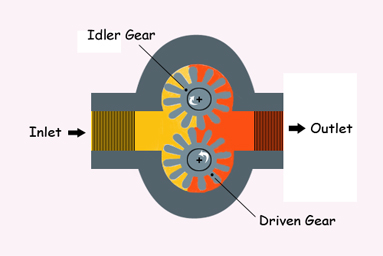
Hydraulic pump working principle is based on the principle of displacement pumps. A hydraulic pump is a primary part of a hydraulic system that transforms the mechanical energy from an engine or motor into hydraulic energy. The hydraulic pump consists of pressure and flow to perform useful work.
A pump flow is a function of speed and displacement (volume). A larger pump can transfer more fluid at once or push on more fluid by spinning a pump faster. Power in hydraulics is a mixture of pressure and flow. By doubling pressure while the flow is the same, the horsepower doubles. On the other hand, by doubling the flow while applying the same pressure, the horsepower is also doubled.
Hydraulic Pumps Basics
A hydraulic pump is a mechanical machine that converts mechanical power from an external source into hydraulic energy in the form of a combination of flow and pressure. It produces flow with enough power to overcome the load pressure at the pump outlet.
When the hydraulic pump is running, it generates a vacuum at the inlet of the pump, which pushes liquid from the reservoir into the inlet line. The liquid is then delivered to the pump outlet by mechanical action, and finally, it is directed into the hydraulic system.
Hydraulic pumps used in hydraulic systems can be hydrostatic or hydrodynamic. A hydrostatic pump is a positive displacement pump, while a hydrodynamic pump can be a fixed displacement pump or a variable displacement pump. In the case of fixed displacement pumps, the displacement (i.e. flow through the pump per pump rotation) cannot be adjusted. In the case of variable displacement pumps, the construction is more complicated, allowing the displacement to be adjusted.
Hydrodynamic pumps are more common in everyday life. All kinds of hydrostatic pumps operate on the principle of Pascal’s law.
Working Principle of Hydraulic Pumps
In a positive-displacement pump, the same amount of liquid is displaced or delivered for each rotating cycle of the pumping component. Consistent delivery through every cycle is achievable due to the close-tolerance fit between the pumping component and the pump case. This means that the liquid amount slipping through the pumping element in a positive-displacement pump is small and negligible compared to the maximum theoretical delivery.
As a result, the delivery in each cycle remains relatively constant, regardless of pressure changes against which the pump operates. Note that if fluid slippage is significant, the pump will not work properly and need to be repaired or replaced.
Positive displacement pumps can be fixed or variable displacement. The pump output in a fixed displacement type remains constant per each pumping cycle at a certain pump speed. However, the output of a variable displacement pump can be altered by changing the displacement chamber geometry.
Hydrostatic pumps refer to positive displacement pumps, and hydrodynamic pumps are referred to as non-positive displacement. Hydrostatic means that the pump turns mechanical energy to hydraulic energy with a comparatively small volume and velocity of the liquid. While with a hydrodynamic pump, the velocity of the liquid and its movement are large, and the outlet pressure is dependent on the velocity of the liquid flow. Most hydraulic pumps work based on positive displacement principles.
We can define the hydraulic efficiency and mechanical efficiency of a hydraulic pump as:
\eta _{hydraulic}=\frac{Q_{actual}}{Q_{theoretical}}\times100%
\eta _{mechanical}=\frac{T_{Theoretical}}{T_{actual}}\times100%
In the above equations, Q is flow rate output and T is torque to drive.
Positive Displacement Pumps
A positive displacement pump causes the liquid to move by trapping a fixed quantity and pushing (displacing) it into the discharge line.
Some positive displacement pumps apply an expansion cavity on the suction side and a contraction cavity on the discharge side. When the cavity expands on the suction side, liquid flows into the pump, and when the cavity shrinks, the liquid flows out of the discharge. The volume is constant in each operation cycle.
Unlike centrifugal pumps, positive displacement pumps can theoretically generate the same flow at a certain speed (rpm) regardless of the discharge pressure. Therefore, positive displacement pumps can be called constant flow machines. This is while a slight increase in internal leakage occurs when the pressure increases. So, the leakage prevents a real constant flow rate.
A positive displacement pump cannot work against a closed valve on the pump discharge side, as it does not have a shutoff head like centrifugal pumps. Running against a closed discharge continues to generate flow, and thus, the pressure in the discharge line elevates until the line bursts, or the pump is seriously damaged, or both. Therefore, on the discharge side of the positive displacement pump, a relief or safety valve is necessary.
The relief valve can be installed internally or externally. The pump manufacturers usually provide the choice to supply internal relief or safety valves. Typically, an internal valve is applied only as a safety precaution. However, an external relief valve with a return line to the suction line or supply tank increases the safety of both humans and equipment.
Gear Pumps
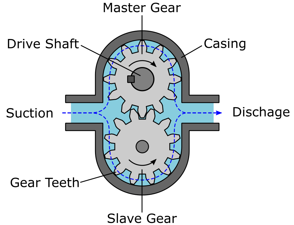
Gear pumps (with external teeth) are positive displacement (or fixed displacement) pumps with a simple working and economic structure. The displacement volume of hydraulic gear pumps can be from about 1 to 200 milliliters. They have lower volumetric efficiency than gear pumps, vane pumps, and piston pumps. These pumps generate pressure by the meshing of the gear teeth, pushing the fluid around the gears to apply the pressure to the outlet side.
Some gear pumps can be much noisier than other types, but modern models of gear pumps are much more reliable and quieter than older ones. This is partly due to designs including split gears, helical gear teeth, and higher quality tooth formations that mesh and unmesh more smoothly. These features reduce pressure ripple and related detrimental issues.
Another strength of the gear pump is that severe failure is much less than most other hydraulic pump types because the gears constantly wear down the housing and main bushings. It decreases the volumetric efficiency of the pump until it is completely useless. This often causes the unit to stop working or break down.
Rotary Vane Pumps
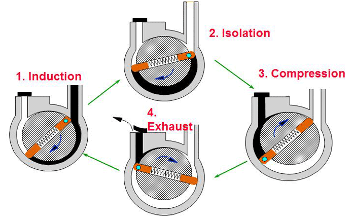
An essential point of these positive displacement pumps is how the vanes come in contact with the pump housing, and the vane tips are machined at this point. Several types of “lip” designs are applied, and the main purpose is a tight sealing between the inner side of the housing and the vane while minimizing wear and metal-to-metal contact. The vane is pulled out of the center of rotation toward the pump housing using spring-loaded vanes, or in traditional efforts, vanes were loaded hydrodynamically through a pressurized system fluid.
Screw Pumps
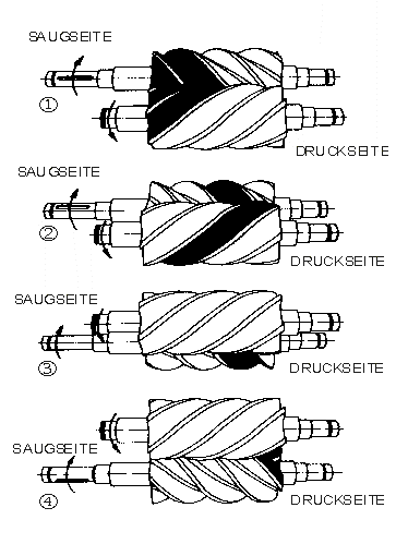
Screw pumps are positive (or fixed) displacement pumps that consist of two Archimedes screws intermeshing and being enclosed inside the same chamber. These pumps are utilized for high flow rates at comparatively low pressures up to 100 bars. They have been used on board ships in which a continuous pressure hydraulic system has been extended throughout the ship, mainly to control ball valves but also to drive the steering gear and other systems. The benefit of the screw pumps is their low noise level. However, the efficiency of the screw pumps is not high.
The main problem with screw pumps is that the hydraulic reaction force is transferred in a direction axially opposed to the flow direction.
Two ways are recommended to overcome this issue:
- Place a thrust bearing below each rotor;
- Make a hydraulic balance by leading a hydraulic force to a piston beneath the rotor.
Screw pumps types include:
- Single-end
- Double-end
- Single rotor
- Multi rotor timed
- Multi rotor untimed.
Piston Pumps
A piston pump is a positive displacement pump in which the high-pressure seal reciprocates with the piston. Piston pumps are utilized to transfer liquids or compress gases. They can work over a broad range of pressures. Operation with high pressure can be accomplished without a significant effect on flow rate. In cases of viscous media, piston pumps can deal properly with media containing solid particles.
A piston pump operates using a piston cup, an oscillation mechanism where the down-strokes make pressure differentials, filling the pump chambers, where the up-stroke pumps the fluid out for use. These pumps are usually applied in conditions where a high, consistent pressure is needed, such as water irrigation or delivery systems.
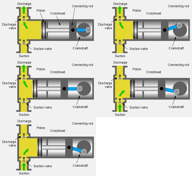
The two types of piston pumps are: lift pumps and force pumps. Both may operate by hand or an engine.
Lift Pump
The upstroke of the piston of the lift pump draws liquid into the lower part of the cylinder through a valve. In the downstroke, the liquid passes through valves installed in the piston into the upper section of the cylinder. The next upstroke discharges the liquid from the upper part of the cylinder through a spout. Lift pumps are limited by the height of water supported by air pressure against a vacuum.
Force Pump
The upstroke of the piston of the force pump draws liquid into the cylinder through an inlet valve. On the downstroke, the liquid is discharged into the outlet pipe through an outlet valve.
Variable Displacement Pump
With a variable displacement pump, the displacement or volume of the pumped liquid per revolution of the pump shaft can be varied while the pump is working.
Reversible variable displacement pumps are those that can work as a hydraulic motor and turn fluid energy into mechanical energy.
In a variable displacement pump, as the normal vector to the swashplate is set parallel to the rotation axis, no movement of the pistons occurs in their cylinders, therefore, there is no output. The movement of the swashplate controls the output of the pump from zero to the maximum amount. Two types of variable displacement axial piston pumps are direct displacement control pumps and servo control pumps.
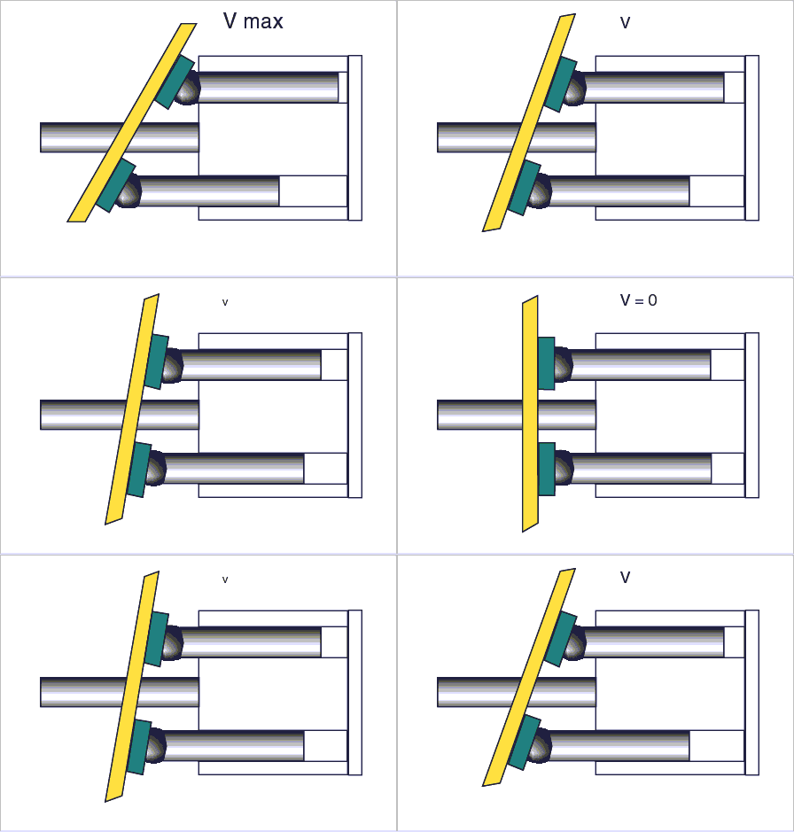
A direct displacement control pump is an axial piston pump type with direct displacement control, which uses a mechanical lever connected to the swashplate of the axial piston pump. Higher pressures of the system need more power to move that lever. Thus, direct displacement control is only proper for light or medium-duty pumps. On the other hand, heavy-duty pumps need servo control.
A direct displacement control pump includes linkages and springs and sometimes magnets instead of a shaft to a motor placed outside the pump, which leads to a reduction in the number of moving parts. Moreover, the parts are kept protected and lubricated, and the resistance against the flow of liquid is reduced.
Axial Piston Pumps
The most common variable displacement pump applied in vehicle systems is the axial piston pump. These pumps have several pistons in cylinders that are parallel to each other and rotate around a central shaft. A swashplate is attached to the pistons at one end. As the pistons turn, the angle of the plate moves them in and out of the cylinders. At the opposite end from the swashplate, a rotary valve alternately joins each cylinder to the liquid supply and delivery lines.
By altering the angle of the swashplate, the stroke of the piston can be changed continuously. If the swashplate is perpendicular to the rotation axis, no liquid will flow. On the other hand, if the swashplate is at a sharp angle, a large quantity of liquid will be pumped. In some pumps, the swashplate is allowed to move from the zero position in both directions, pumping liquid in both directions without reversing the pump rotation.
An effective type is the bent axis pump. The bent axis decreases side loads on the pistons.
By placing springs inline with the piston, a piston pump can be made as a variable displacement pump. The displacement is not positively regulated but reduces as back-pressure rises.

