Difference Between Linear and Nonlinear Circuits- The linear and non-linear components are used to construct electrical devices. A rudimentary understanding of linear and nonlinear circuits is required to comprehend the basic design of these devices. In this post, we’ll look at what linear and nonlinear circuits are, as well as their differences, elements of linear and nonlinear circuits, and some examples.
What is the Main Difference Between Linear and Nonlinear Circuits?
The relation between the input and output signal is what distinguishes a nonlinear circuit from a linear circuit. For all input signal rates, if you determine the output signal versus the input signal for a linear circuit, the figure will be a straight line. The output of a non-linear circuit will not be a straight line. Instead, a curve will be the output.
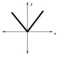
In a nonlinear circuit, another possibility is that the output is a piecewise function of the input. Even though each part of the function is linear within a certain range of inputs, piecewise functions are nonlinear. The circuit is nonlinear by definition since the output signal is discontinuous in different locations.
Consider a full-wave rectifier circuit for power conversion if this sounds strange. The output of the rectifier circuit is simply the absolute value of the input (before being smoothed using a capacitor), and the function abs(x) does not satisfy the mathematical definition of a linear function. After smoothing the output with a capacitor, the result is a DC signal with some non-sinusoidal ripple. You transmit an AC sinusoidal signal, but you get a DC voltage and a non-sinusoidal wave in return.
To achieve the necessary nonlinear response in the output, this form of the non-linear circuit takes advantage of the response in nonlinear circuit parts (specifically, 4 diodes). The linear and nonlinear components of a typical circuit network contain linear and nonlinear circuit elements, respectively. When a linear segment of a network’s output is fed into a nonlinear circuit element, the circuit’s total output becomes nonlinear. There are only a few exceptions (i.e. putting the output from a differentiator into an integrator). Visit here to see the difference between linear and non-linear circuits fundamentally.
Some people argue that a linear circuit with a transient response (for example, an RLC network) is essentially a non-linear circuit. This is not the situation in reality. In this arrangement, the relation between the output current and the driving voltage/current remains linear.
Because the transient response is a nonlinear function of time rather than the input voltage or current, the circuit is nevertheless classified as linear. We still have a linear response under AC driving because the response is a complex linear function of the input signal amplitude and frequency (i.e. simple multiplication).
What are Linear and Nonlinear Circuits?
Simply put, a linear circuit is an electric circuit whose characteristics such as resistance, capacitance, inductance, and others remain constant. A linear circuit is one in which the parameters of the circuits do not change with respect to voltage and current.
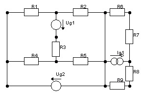
A linear circuit, in simple terms, is an electric circuit with constant circuit parameters (resistance, inductance, capacitance, waveform, frequency, and so on).
The word “linear” denotes “together with a straight line” in its most basic sense. A linear circuit, as the name implies, has linear properties between current and voltage, implying that the current flowing through a circuit is proportional to the applied voltage.
When the applied voltage is increased, the current flowing through the circuit increases as well, and vice versa. The circuit output characteristic curve will appear as a straight line if we draw it between Current and Voltage (Diagonal).
The non-linear circuit is also an electric circuit, with parameters that differ depending on the current and voltage. Non-linear circuits are those in which the parameters such as waveforms, resistance, inductance, and so on are not constant.
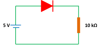
Difference Between Linear and Non-linear Circuits
In general, the term “linear” refers to a straight line that seems to be diagonal and describes linear qualities between voltage and current. In other words, the current flowing through the circuit is proportional to the voltage. When the voltage is increased, the current flow in the circuit also increases, and vice versa. The linear circuit’s output characteristics are illustrated below as a relation between current and voltage.
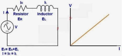
The output response of a linear circuit is precisely proportional to the input. The applied sinusoidal has the frequency “f,” and the output indicates that the voltage between the two sites has the same frequency as the applied sinusoidal.
The output characteristic of a nonlinear circuit looks like a curve line that runs between voltage and current, as shown in the diagram below.
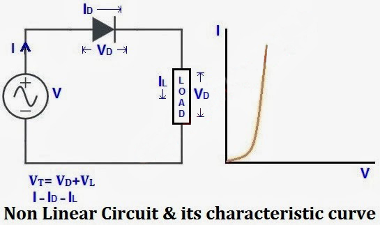
Another difference between linear and nonlinear circuits is how the circuit is solved. In linear circuits, the circuit is easily solved using a simple technique and a calculator, and when compared to non-linear circuits, the linear circuit is straightforward to solve.
Non-linear circuits are more difficult to solve than linear circuits because they demand a lot of data and knowledge. We can now model and analyze the output curves of linear and nonlinear circuits using circuit simulation tools such as Multisim, MATLAB, and PSpice, due to significant advancements in technology.
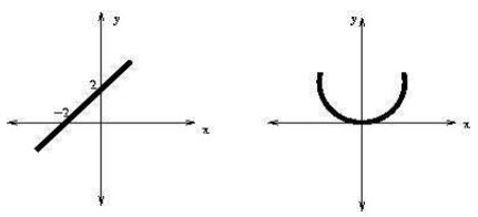
We can identify the difference between linear and nonlinear circuits by using the linear and nonlinear equations. They are Y=X+2 and Y=X2.
The graph version of the two equations above is illustrated in the diagram below. It is a linear equation if any of the equations are represented by a straight line in the graph. The equation is nonlinear if it is a curved line.
The piecewise linear is represented by the equation below, and the piecewise linear x-y axis graph is also illustrated below. Because we can’t express the equation as follows, we consider it a nonlinear equation.
Elements of Linear and Nonlinear Circuits
Nonlinear elements are electrical elements in nonlinear circuits that do not have a linear relation between current and voltage. A diode is an example of a nonlinear element, and an electric circuit with no nonlinear elements is known as a linear circuit. Transistors, various semiconductor devices, vacuum tubes, iron core inductors, and transformers are examples of nonlinear elements. Piecewise linear describes the presence of linear curves in nonlinear curves.
The linear element in linear circuits is also an electrical element, and the voltage and current will have a linear connection. The most common linear element is the resistor, which is followed by capacitors and air-core inductors.
Examples of Linear Circuits
Resistance and resistive circuits, inductor and inductive circuits, and capacitor and capacitive circuits are all examples of linear circuits.
Examples of Nonlinear Circuits
Diode, transformer, iron core, inductor, and transistor are examples of nonlinear circuits with nonlinear components.
Applications of the Linear and Nonlinear Circuits
In electrical circuits, linear and nonlinear circuits are utilized. We can determine voltage drop and current using these circuits.
Signal Distortion and Feedback in Nonlinear Circuits
One of the most important properties of a nonlinear circuit is its capacity to shape (or distort) an input signal, whether sinusoidal or not. The shift from a linear zone with low input voltage/current into a nonlinear region with high input voltage/current can distort a signal in both the frequency and temporal domains. This impact is significant in both the frequency and time domains in circuits with saturation and feedback.
Consider the operational amplifier, which is a common non-linear circuit component. The output will be a linear function of the input when driven with a low-level input signal. The output will level out and saturate at a set value when the input is high. This can be used to saturate an input sinusoidal signal after it reaches a certain saturation level, effectively turning the sinusoidal wave into a square wave (e.g. a Schmitt trigger circuit). A key aspect of linear and nonlinear filter design is the ability to modify multiple frequencies as a function of the input signal strength.
In an amplifier or other circuit having non-linear elements, positive feedback can cause instability in the nonlinear response. It’s worth noting that instability isn’t limited to nonlinear circuits; in the presence of feedback, even linear time-invariant circuits can become unstable. Finding the poles and zeros in the transfer function for your circuit will help you find regions of stability, regardless of the type of circuit you’re dealing with. For a linear circuit, this can be done easily by hand, but for a nonlinear circuit, it must be done numerically using a circuit simulator.

If you want to investigate the behavior of nonlinear circuits on your PCB, you’ll require PCB layout and design software that incorporates the circuit and signal analysis capabilities you’ll need. You can create linear and nonlinear circuits with Allegro PCB Designer and a comprehensive array of design and analysis tools. You’ll get access to a vast component library that includes electrical models that work well with simulation tools.
This post has explained what linear and nonlinear circuits are, as well as the difference between linear and nonlinear circuits. We hope that reading this post has given you a basic understanding of linear and nonlinear circuits. Please feel free to leave a comment in the box below if you have any questions about this post or how to implement electrical projects for engineering designers.
Buy Equipment or Ask for a Service
By using Linquip RFQ Service, you can expect to receive quotations from various suppliers across multiple industries and regions.
Click Here to Request a Quotation From Suppliers and Service Providers
Read More on Linquip
- What Are Resistors for LED Circuits? (Clear Guide)
- What is Linear Circuit? Example & Diagram
- What is Resistive Circuit? Example & Diagram
- What is Capacitive Circuit? Formula & Function
- What is LC Circuit? Formula, Equitation & Diagram
- What is RL Circuit? Formula, Equitation & Diagram
- What is RC Circuit? Formula, Equitation & Diagram
- Types of Resistor: Classification, Application, and Finally Clarification
- What is Parallel Circuit? Definition & Example
- What is Series Circuit? Definition & Example
- What is a Closed Circuit? Definition & Example
- What is a Short Circuit? A Clear Definition & Protection Guide
- What is Open Circuit? Diagram & Example
- What is Inductive Circuit?
- Difference Between Linear and Nonlinear Circuits
- Types of Electric Circuits: All Classification with Application
- What are the Differences Between Series and Parallel Circuits?
- Types of Electric Circuits: All Classification with Application
- How does a Circuit Breaker Work?
- What are Vacuum Circuit Breakers?
- Difference Between Isolator and Circuit Breaker: Ultimate Guide
- Difference Between Relay and Circuit Breaker: Everything You Need to Know
- Difference between Series and Parallel Circuits | What are they Completely?



Thanks for the pass criteria of my assignment!!!! batty boys!!!
Thanks for visiting our website and leaving your comment, Raja! We hope to hear from you again in our other posts.
Thanks for the pass criteria of my assignment!!!!
Thanks for visiting our website, Raja! We also encourage you to visit the Linquip website, where you can find numerous industrial equipment, along with companies and experts.