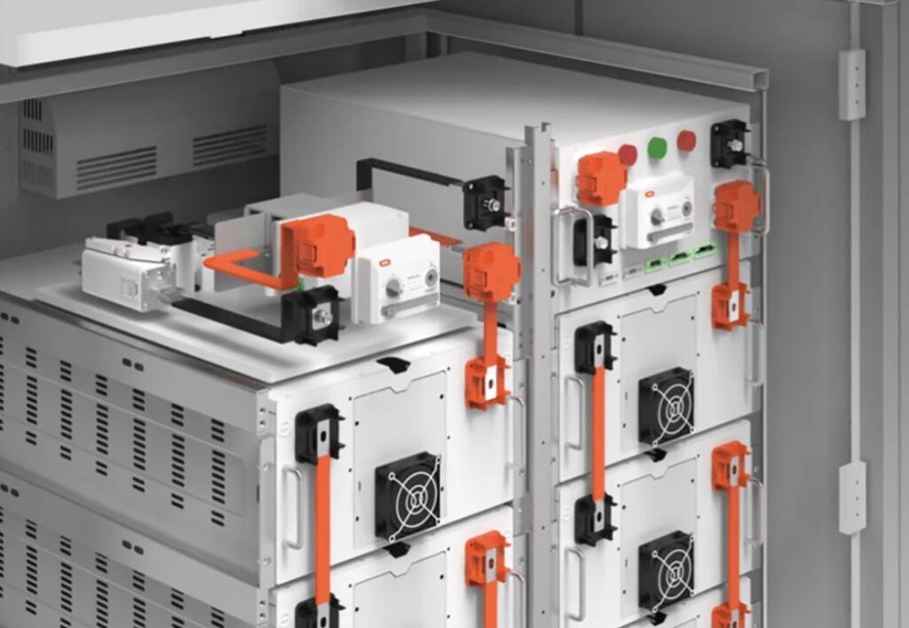
Power distribution design often reaches a point where engineers must choose between insulated cable and a busbar-based conductor system. Both can carry substantial current safely when correctly selected and installed. The better option depends on electrical duty, enclosure geometry, fault level, installation method, maintenance needs and how much flexibility the project requires. GRL Copper, a manufacturer of copper busbars and flexible connectors, is one example of a supplier working with these types of high-current connection systems.
Copper busbar becomes attractive when current rises, space tightens or a compact and repeatable connection layout is needed. Cable remains valuable where routes are long, equipment positions may change or conductors must pass through irregular pathways. The real question is not whether busbar is universally better, but when its electrical and mechanical characteristics solve a particular design problem more effectively.
Start With the Current Path
A useful specification begins by mapping how power moves through the system. Engineers should identify incoming feeds, branch points, switching devices, transformers, converters, protective devices and major loads before selecting the conductor arrangement.
Cable is naturally suited to point-to-point connections. It can be routed around obstacles and through trays or containment. Busbar is more structured. A rigid copper bar can form a common distribution spine inside switchboards, power distribution units, inverters, control cabinets and other high-current assemblies.
That structured geometry can reduce the number of separate conductors and lets the power path become part of the equipment layout rather than wiring added after the mechanical design is complete.
High Current and Power Density
One of the strongest reasons to consider copper busbar is high current in a restricted volume. Copper combines high electrical conductivity with the ability to be formed into flat sections that offer substantial surface area.
That geometry can aid thermal management, but current rating cannot be assumed from cross-sectional area alone. Ambient temperature, enclosure ventilation, bar orientation, spacing, joint resistance, permitted temperature rise and insulation all matter.
For this reason, busbar sizing should be based on defined electrical and thermal requirements rather than a simple “amps per square millimetre” rule. A busbar that performs well in open air may behave differently inside a densely packed enclosure.
Compact Equipment and Predictable Geometry
In switchgear and power-electronic assemblies, space is often more valuable than conductor flexibility. Multiple large cables need bend radius, room for lugs, termination access, cleats and clearance around each connection. Those requirements can consume significant enclosure volume.
A formed copper busbar can follow a controlled route between fixed components while keeping connection points in known positions. Holes, bends, offsets, surface treatments and insulation can be designed around the equipment layout.
This is where early collaboration with a copper busbar manufacturer can be useful. Electrical and mechanical teams can evaluate conductor geometry alongside terminal locations, clearances, assembly sequence and thermal requirements instead of choosing the conductor after the cabinet is already fixed.
Short-Circuit Forces Matter
Normal operating current is only one design condition. During a short circuit, conductors can experience large electromagnetic forces. A busbar system therefore needs suitable supports, insulators, spacing and joints to withstand the prospective fault current for the required duration.
Rigid busbar has useful mechanical strength, but that does not remove the need for calculation. Support spacing, bar dimensions, phase separation and peak current influence mechanical stress.
Cable systems have their own short-circuit requirements. Large cables may require cleating or restraint so that fault forces do not cause excessive movement. In both cases, the conductor and its supports should be treated as one engineered system.
Connections and Maintenance
Every joint creates an interface where resistance can rise if contact surfaces, pressure, hardware or installation practice are poor. Busbar systems often use bolted, clamped or welded connections. Cable systems add lugs, crimps, glands and bolted terminals.
Busbar can be advantageous in repeatable factory-built equipment because joint positions and hardware can be standardised. Cable can be more forgiving during field installation because lengths can be adjusted and routes modified on site.
A factory-assembled power cabinet with controlled production processes may therefore favour precision busbar. A retrofit in an existing plant, where dimensions are uncertain and access is difficult, may favour cable.
Thermal Expansion and Vibration
Rigid copper busbar works best where connection points remain mechanically stable. Problems can arise when equipment moves because of vibration, manufacturing tolerance, or thermal expansion.
Designers do not always need to choose between rigid busbar and cable. A hybrid arrangement can use a rigid busbar for the main distribution path and a flexible copper section near equipment that moves or expands.
Flexible laminated or braided connections can reduce mechanical loads transferred into terminals while still providing a high-current path. Such interfaces are useful around transformers, battery systems, converters, generators and machinery. Where movement is frequent or equipment must be disconnected regularly, cable may remain simpler.
Frequency and Power-Electronics Effects
At direct current and lower-frequency AC, resistance and temperature rise dominate many sizing decisions. As frequency and switching speed increase, conductor geometry becomes more important.
Skin effect and proximity effect can influence AC resistance, particularly in thick conductors and closely spaced phases. In power-electronic systems, closely coupled positive and negative bus structures can also help reduce loop inductance, which matters when fast-switching devices produce high rates of current change.
Engineers working with inverters, UPS systems, battery energy storage or high-power converters should therefore consider electrical parasitics as well as ampacity.
When Cable Is the Better Choice
Copper busbar should not be specified simply because current is high. Cable often remains preferable when:
- the route is long or passes through multiple trays and elevations;
- equipment locations may change during installation or future upgrades;
- field-routing flexibility is more valuable than compact geometry;
- the conductor must tolerate regular movement;
- standard cable accessories simplify installation and replacement.
Cable is familiar to a wide installation workforce, and standard sizes are readily available in many markets. For distributed systems, that practical advantage can outweigh busbar’s packaging benefits.
Cost Should Be Viewed Across the Project
Material price alone can be misleading. A custom busbar may cost more per component than a length of cable, yet it can reduce routing space, termination count or assembly time in repeat production. Conversely, cable may avoid tooling or custom fabrication costs on low-volume projects.
The comparison should therefore include enclosure size, installation labour, inspection access, replacement strategy and production volume rather than conductor price alone.
A Practical Specification Checklist
Before choosing copper busbar over cable, verify:
- continuous current and permitted temperature rise;
- voltage and insulation requirements;
- prospective short-circuit current and withstand duration;
- enclosure temperature, ventilation and conductor spacing;
- terminal locations and mechanical tolerances;
- vibration or thermal movement;
- plating, insulation and environmental protection;
- maintenance access and assembly requirements;
- AC-frequency or switching effects where relevant;
- applicable equipment and safety standards.
Conclusion
Copper busbar is most compelling when a project combines high current, tight packaging, fixed connection points and a need for a controlled, repeatable distribution layout. It can simplify high-current connections and give engineers direct control over conductor geometry. Cable remains more adaptable for long runs, irregular routes, retrofits and applications where movement is expected.
Many robust designs use both. Rigid busbar can form the high-current backbone, flexible sections can manage movement at selected interfaces and cable can handle longer or less predictable routes. Treating these options as complementary tools helps engineers select the conductor system that best fits the project’s electrical, thermal, mechanical and installation requirements.