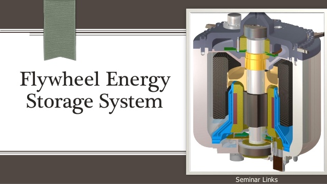
Electric energy is supplied into flywheel energy storage systems (FESS) and stored as kinetic energy. Kinetic energy is defined as the “energy of motion,” in this situation, the motion of a rotating mass known as a rotor, rotates in a near-frictionless environment. When utility power is lost or fluctuates, the inertia of the rotor permits it to continue spinning, converting the kinetic energy into electricity.
A huge spinning cylinder (a rim attached to a shaft) is maintained on a stator – the stationary element of an electric generator – by magnetically levitated bearings in most modern high-speed flywheel energy storage systems. The flywheel system is performed in a vacuum to diminish drag and maintain efficiency. The flywheel is coupled to a motor-generator that uses modern power electronics to communicate with the utility grid.
How Flywheel Energy Storage Systems Work?
Flywheel energy storage systems employ kinetic energy stored in a rotating mass to store energy with minimal frictional losses. An integrated motor–generator uses electric energy to propel the mass to speed. Using the same motor-generator, the energy is discharged by pulling down the kinetic energy. The quantity of energy stored is related to the object’s moment of inertia times its angular velocity squared.
The flywheel must spin at the fastest possible speed to maximize the energy-to-mass ratio. Rapidly rotating objects experience considerable centrifugal forces; yet, while dense materials may store more energy, they also experience higher centrifugal forces, making them more prone to failure at lower rotational speeds than low-density materials. As a result, tensile strength is more significant than material density. Low-speed flywheels are made of steel and rotate at speeds of up to 10,000 revolutions per minute.
Advanced FESS utilizes four main aspects to produce attractive energy density, high efficiency, and minimal standby losses (during time periods ranging from a few minutes to several hours):
- Rotating mass built of high-strength-to-weight-ratio fiberglass resins or polymer compounds.
- To reduce aerodynamic drag, a mass that functions in a vacuum is used.
- Rotating mass with a high frequency of rotation.
- To accommodate high rotational speeds, air or magnetic suppression bearing technology is used.
Advanced FESS have a rotational frequency of more than 100,000 RPM and tip speeds of more than 1000 m/s. FESS are ideal for high-power, low-energy applications with a lot of cycles.
They also have a number of advantages over chemical energy storage. They have a high energy density and a long lifespan, allowing them to be cycled frequently without losing performance. They also feature lightning-quick response and ramp times. They may even go from full discharge to full charge in a matter of seconds. FESS are becoming more relevant in high-power, low-energy applications. They’re especially appealing for applications that require a lot of cycling because they only have a small life reduction when used frequently (i.e., they can undergo many partial and full charge-discharge cycles with trivial wear per cycle).
Electric service power quality and dependability, ride-through while gen-sets start-up for longer-term backup, area regulation, quick area regulation, and frequency responsiveness are just a few of the areas where FESS excel. FESS could also be useful as a component of track-side or onboard regenerative braking systems in hybrid vehicles that stop and start frequently.
The Theory of Flywheel Energy Storage
With reduced frictional losses, FESS uses kinetic energy stored in a spinning mass. The following equation describes the kinetic energy of the system:
E=\frac{1}{2}I \omega^2
where E is the kinetic energy, I is the moment of inertia, and ω represents the angular velocity of the rotating disc; when I or ω increases, the energy of the system raises.
Flywheels, which were once composed of steel, are now built of a carbon fiber composite with high tensile strength and the ability to store significantly more energy. Higher rotational speeds are preferable since the quantity of energy stored in the flywheel is a function of the square of its rotating speed and mass. The best energy-to-mass ratio is achieved by spinning at the highest achievable speed. However, at lower rotational speeds, the flywheel is subjected to large centrifugal forces and may be more prone to failure than lesser density materials.
FESS are connected to a motor-generator that communicates with the utility grid via modern power electronics and run in a vacuum to reduce drag, friction, and energy loss. They are employed in energy grid storage as a reserve for momentary grid frequency adjustment and balancing unexpected variations in supply and demand, as well as when short-term backup power is necessary due to utility power fluctuation or loss.
The built-in motor-generator uses electric energy to propel the rotor up to speed; inertia permits the rotor to maintain spinning, and the kinetic energy is transferred to electricity. Using the same motor as a generator, energy is discharged by pulling down kinetic energy. However, it is not a primary source of energy. Extra grid power is diverted to the flywheels, which are then placed in motion. When the electricity is needed later, the flywheel’s motion is employed to generate power that is supplied back into the grid.
Main Components of Flywheel Energy Storage System
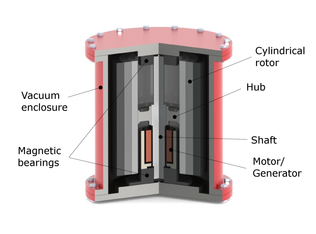
A flywheel is supported by a rolling-element bearing and is coupled to a motor-generator in a typical arrangement. To reduce friction and energy waste, the flywheel and sometimes the motor–generator are encased in a vacuum chamber.
A massive steel flywheel rotates on mechanical bearings in first-generation flywheel energy storage systems. Carbon-fiber composite rotors, which have a higher tensile strength than steel and can store significantly more energy for the same mass, are used in newer systems.
Magnetic bearings are occasionally used instead of mechanical bearings to reduce friction.
The figure below demonstrates the main components of a typical flywheel energy storage system.
Superconducting Bearings Could Be Used in the Future
Low-temperature superconductors were initially dismissed for use in magnetic bearings due to the high cost of cooling. High-temperature superconductor (HTSC) bearings, on the other hand, may be cost-effective and expand the amount of time energy may be stored. The usage of hybrid bearing systems is most likely to come initially. Historically, high-temperature superconductor bearings struggled to deliver the lifting forces required for bigger designs, but they can easily supply a stabilizing force.
As a result, permanent magnets support the load in hybrid bearings, while high-temperature superconductors stabilize it. Because superconductors are ideal diamagnets, they can perform effectively in load stabilization. If the rotor attempts to drift off-center, it is restored by a restoring force caused by flux pinning. This is referred to as the bearing’s magnetic stiffness. Because of the poor stiffness and damping of superconducting magnets, rotational axis vibration might occur, restricting the use of entirely superconducting magnetic bearings for flywheel applications.
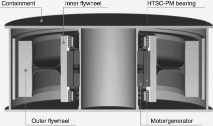
The HTSC can be produced considerably more readily for FESS than for other uses since flux pinning is essential in delivering the stabilizing and lifting force. As long as the flux pinning is strong, HTSC powders can be shaped into any shape. Finding a technique to prevent the reduction in levitation force and gradual fall of the rotor throughout service caused by the flux creep of the superconducting material is an ongoing difficulty that must be overcome before superconductors can offer the entire lifting force for FESS systems.
The Applications of Flywheel Energy Storage
FEES have broad applications from transportation and power supplies to aircraft and even toys. Here we present a comprehensive overview of numerous applications of FEES.
Transportation
Rail Vehicles
Flywheel systems have been employed for shunting and switching in tiny electric locomotives, such as the Sentinel-Oerlikon Gyro Locomotive. Flywheel boosters have been used on larger electric locomotives, such as the British Rail Class 70, to carry them over gaps in the third rail. Advanced flywheels, such as the University of Texas at Austin’s 133 kWh pack, can accelerate a train from a standstill to cruising speed.
The Parry People Mover is a railcar using a flywheel as its power source. It was trialed on the Stourbridge Town Branch Line in the West Midlands, England, for a year on Sundays in 2006 and 2007, with the intention of being implemented as a full service by the train operator London Midland in December 2008, once two units had been ordered. Both units are operational as of January 2010.
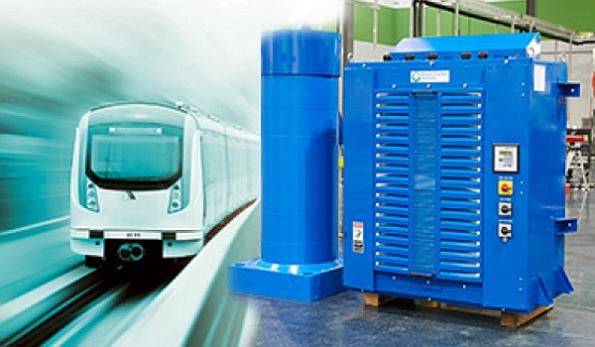
FES can be employed at the lineside of electrified railways to help adjust line voltage, which improves the acceleration of unmodified electric trains and the amount of energy returned to the line during regenerative braking, cutting energy bills. The New York MTA’s Long Island Rail Road is investing $5.2 million in a pilot experiment on the LIRR’s West Hempstead Branch line, following trials in London, New York, Lyon, and Tokyo. These tests and systems use rotors made of a carbon-glass composite cylinder filled with neodymium-iron-boron powder to generate a permanent magnet to store kinetic energy. These spin at up to 37800 revolutions per minute, and each 100 kW unit can store 3.1 kWh of re-usable energy, which is roughly enough to accelerate a 200 metric ton vehicle from zero to 38 kilometers per hour.
Automotive
Flywheel-powered buses, known as gyrobuses, were employed in Yverdon (Switzerland) and Ghent (Belgium) in the 1950s, and research is underway to develop smaller, lighter, cheaper, and higher-capacity flywheel systems. Flywheel systems are intended to be able to replace traditional chemical batteries in mobile applications, such as electric automobiles. Many of the shortcomings of current battery power systems, such as low capacity, long charge periods, hefty weight, and short useable lifespan, would be eliminated with proposed flywheel systems. The experimental Chrysler Patriot may have used flywheels, though this has been disputed.
The use of flywheels in continuously variable gearboxes has also been proposed. Punch Powertrain is currently developing a device like this. Rosen Motors created a gas turbine-powered series hybrid vehicle powertrain in the 1990s that used a 55,000-rpm flywheel to deliver bursts of acceleration that the small gas turbine engine couldn’t. Regenerative braking allowed the flywheel to store energy as well. The flywheel was gimbal-mounted and made up of a titanium hub with a carbon fiber cylinder to reduce gyroscopic impacts on vehicle control. The prototype vehicle was road tested satisfactorily in 1997, but it was never mass-produced.
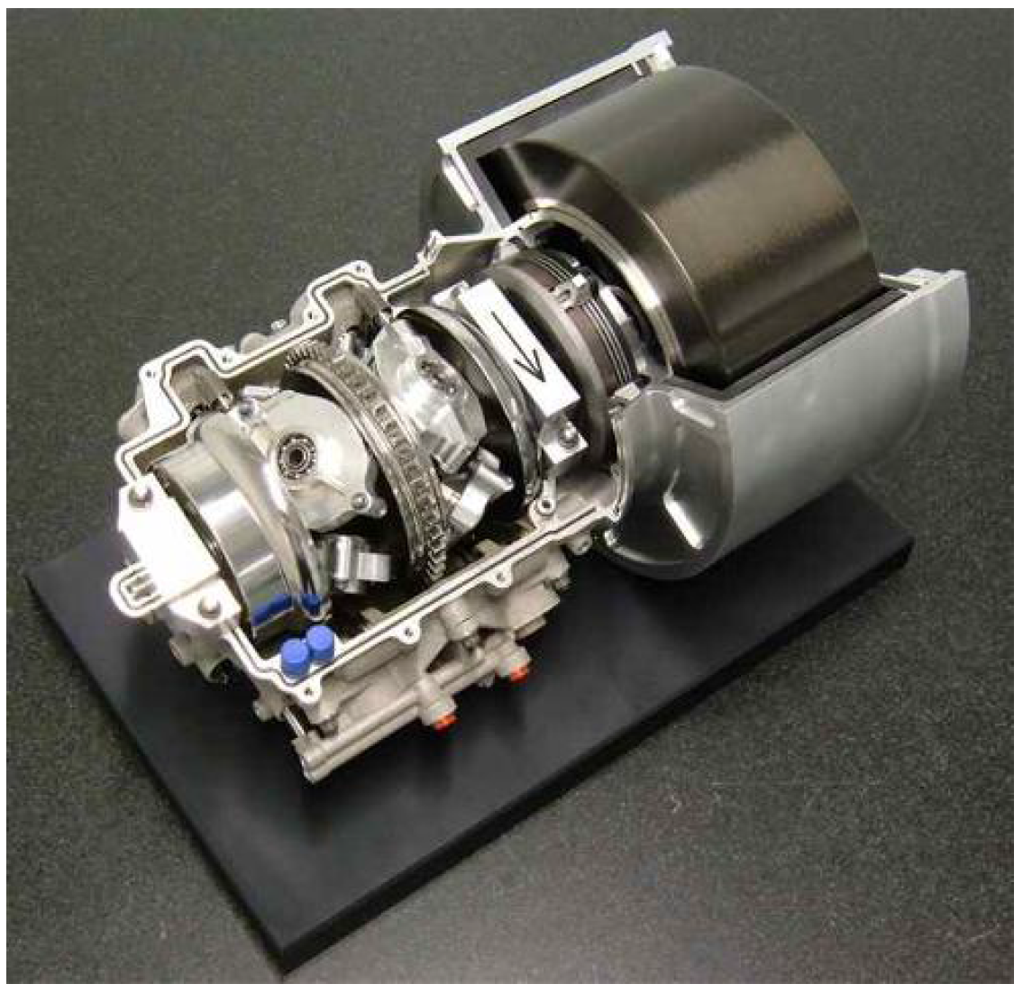
Volvo announced a flywheel system for the S60 sedan’s rear axle in 2013. The front-mounted engine is stopped by braking action, which spins the flywheel at up to 60,000 rpm. Flywheel energy is used to partially or entirely power the vehicle using a unique gearbox. To reduce friction, the 20-centimeter, 6-kilogram carbon-fiber flywheel spins in a vacuum. It provides an 80 horsepower boost and allows it to reach 100 kilometers per hour in 5.5 seconds when paired with a four-cylinder engine, saving up to 25% in fuel consumption over a comparable performance turbo six-cylinder.
Uninterruptible Power Supplies
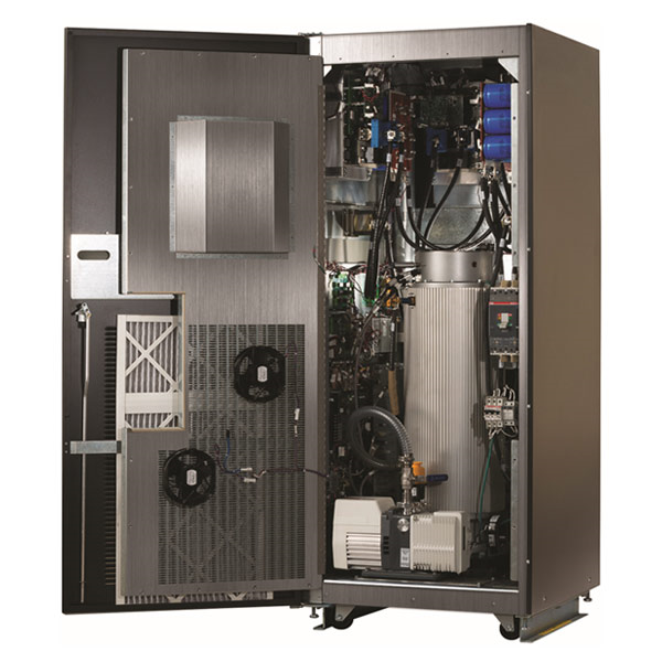
As of 2001, flywheel power storage technologies have storage capacity comparable to batteries and discharge speeds faster than batteries. They’re typically utilized to provide load leveling for large battery systems, such as an uninterruptible power supply for data centers, because they take up less space than battery systems.
Flywheel maintenance is around half the price of regular battery UPS maintenance. The only maintenance required is a basic annual preventative maintenance routine and bearing replacement every five to ten years, which takes around four hours. Newer flywheel systems use maintenance-free magnetic bearings to entirely levitate the spinning mass, removing the need for mechanical bearing maintenance and failure.
A fully fitted flywheel UPS (with power conditioning) costs around $330 per kilowatt in 2009. (for 15 seconds full-load capacity).
Test Laboratories
Circuit breakers and similar device testing facilities have long been a niche market for flywheel power systems: even a simple domestic circuit breaker can be rated to interrupt a current of 10000 or more amperes, and bigger units can have interrupting ratings of 100000 or 1000000 amperes. If these tests were performed directly from building power, the massive transient loads produced by purposefully driving such devices to demonstrate their ability to terminate simulated short circuits would have undesirable impacts on the local grid. A laboratory like this will typically contain many huge motor-generator combinations that may be spun up to speed for several minutes before a circuit breaker is tested.
You can find more information about flywheel applications in test laboratories by watching this video.
Aircraft Launching Systems
Flywheels will collect energy from the ship’s power source and deliver it quickly into the electromagnetic aircraft launch system on the Gerald R. Ford-class aircraft carrier. The shipboard power system is unable to provide the high power transients required to launch aircraft on its own. At 6400 rpm, each of the four rotors will store 121 MJ (34 kWh). In 45 seconds, they can store 122 MJ (34 kWh) and release it in 2–3 seconds. The flywheel energy densities are 28 kJ/kg (8 Wh/kg), omitting the torque frame, and 18.1 kJ/kg (5 Wh/kg) with the stators and casings.
NASA G2 Flywheel for Spacecraft Energy Storage
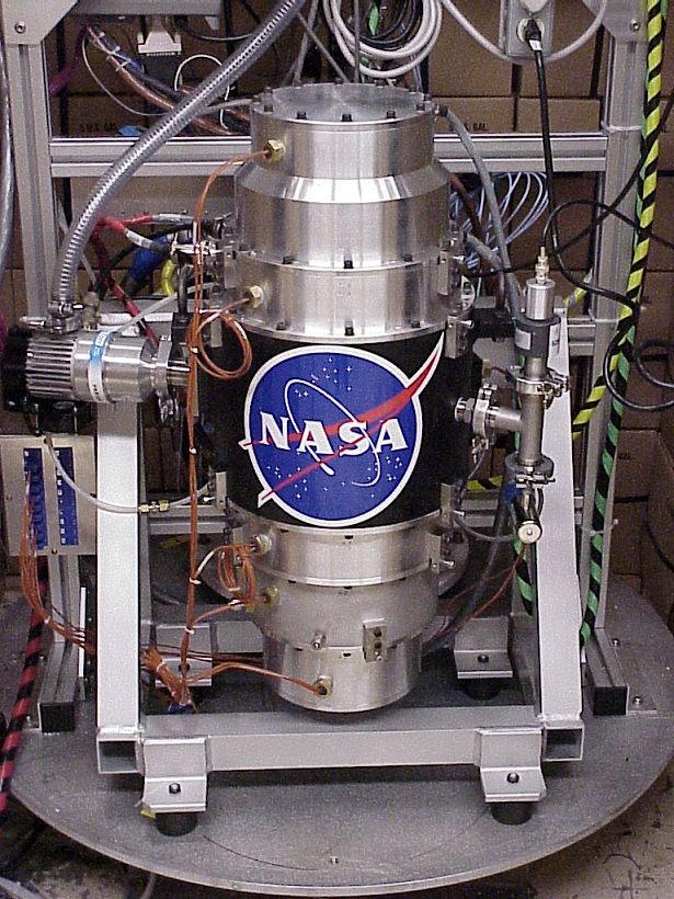
This was a NASA Glenn Research Center-funded design intended for component testing in a laboratory setting. It had a carbon fiber rim placed on magnetic bearings with a titanium hub designed to spin at 60,000 rpm. The maximum weight allowed was 250 pounds. The battery had a capacity of 525 W-hr (1.89 MJ) and could be charged or discharged at a rate of 1 kW. On September 2, 2004, the operational model in the photograph at the top of the page ran at 41,000 rpm.
Pulse Power
Flywheel Energy Storage Systems are used in a wide range of applications, including grid-connected energy management and uninterruptible power supply. With the advancement of technology, the FESS application is undergoing rapid renovation. High-powered weapons, airplane powertrains, and shipboard power systems are examples of systems that require a lot of power for a small amount of time, such as a few seconds or even milliseconds.
Because of its tremendous energy and power densities, the compensated pulsed alternator (compulsator) is one of the most common options of pulsed power supply for fusion reactors, high-power pulsed lasers, and hypervelocity electromagnetic launches. Compulsators (low-inductance alternators) work in a similar way to capacitors in that they can be spun up to produce pulsed power for railguns and lasers. Only the huge rotor of the alternator stores energy rather than a separate flywheel and generator. A homopolar generator is another term for a homopolar generator.
Grid Energy Storage
Flywheels are occasionally utilized as a short-term spinning reserve for grid frequency management and balancing supply and demand fluctuations. Flywheels provide a number of advantages over traditional energy sources such as natural gas turbines, including no carbon emissions, faster response times, and the flexibility to purchase power during off-peak hours. The operation is quite similar to that of batteries in the same application; the main distinction is cost.
In 2011, Beacon Power installed a 5 MWh (20 MW in 15 minutes) flywheel energy storage plant in Stephentown, New York, and a similar 20 MW system in Hazle Township, Pennsylvania, in 2014.
In 2014, Minto, Ontario, Canada, opened a 2 MW (for 15 minutes) flywheel storage plant. The NRStor flywheel system uses ten rotating steel flywheels on magnetic bearings.
Amber Kinetics, Inc. has signed a deal with Pacific Gas and Electric (PG&E) to build a 20 MW/80 MWh flywheel energy storage plant in Fresno, California, with a four-hour discharge time.
Toys
Simple flywheel motors are used to power numerous toy vehicles, trucks, railroads, action toys, and other toys.
Wind Turbines
Flywheels can be utilized to store energy generated by wind turbines during off-peak periods or when wind speeds are particularly high.
Beacon Power started testing their Smart Energy 25 (Gen 4) flywheel energy storage device at a wind farm in Tehachapi, California, in 2010. The system was built for the California Energy Commission as part of a wind power/flywheel demonstration project.
Toggle Action Presses
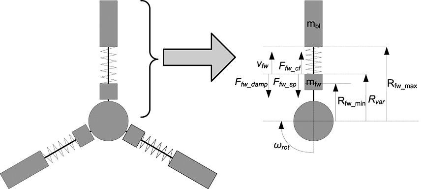
Toggle action presses are still widely used in industry. An extremely powerful crankshaft and a heavy-duty connecting rod are typically used to drive the press. Electric motors drive big and heavy flywheels, but the flywheels only turn the crankshaft when clutches are engaged.
Comparison to Electric Batteries
Flywheels are less sensitive to temperature fluctuations, can function over a far larger temperature range, and are immune to common problems disturbing chemical rechargeable batteries. They’re also less likely to harm the environment because they’re mostly constructed of inert or benign materials. Another advantage of flywheels is that the exact quantity of energy stored may be determined simply by measuring the rotation speed.
Unlike conventional batteries, which have a limited lifespan (about 36 months in the case of lithium-ion polymer batteries), a flywheel has the potential to function indefinitely. For more than two centuries, flywheels created as part of James Watt steam engines have been in continuous use. Many working examples of ancient flywheels, which were mostly employed in milling and pottery, may be found in Africa, Asia, and Europe.
The majority of current flywheels are sealed devices that require little maintenance over their service life. Magnetic bearing flywheels in vacuum enclosures do not require bearing maintenance and hence outperform batteries in terms of total lifetime and energy storage capacity. Due to wear, flywheel systems with mechanical bearings will have a limited lifespan.
High-speed shrapnel from high-performance flywheels can kill bystanders. While batteries can catch fire and spew chemicals, bystanders usually have enough time to evacuate and avoid harm.
Because the energy stored by a flywheel is related to its angular mass and the square of its spinning speed, the physical arrangement of batteries can be built to fit a wide variety of layouts, whereas a flywheel must occupy a minimum area and volume. Because the mass of a flywheel reduces as it gets smaller, the speed must increase, putting more stress on the components. A flywheel may not be a practical solution where space is limited (for example, under the chassis of a train).
Read More In Linquip

