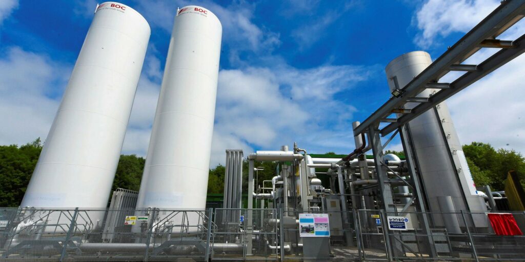
Liquid Air Energy Storage (LAES) applies electricity to cool air until it liquefies, then stores the liquid air in a tank. The liquid air is then returned to a gaseous state (either by exposure to ambient air or by using waste heat from an industrial process), and the gas is used to turn a turbine and generate electricity. LAES systems rely on off-the-shelf components with long life spans (30 years or more), reducing the chance of technology failure. Cryogenic Energy Storage (CES) is another name for liquid air energy storage (LAES). The term “cryogenic” refers to the process of creating extremely low temperatures.
How Does Liquid Energy Storage Work?
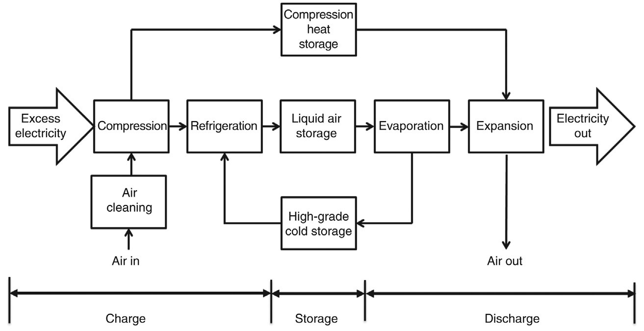
A typical LAES system follows a three-step process. The charging process is the first step, in which excess (cheap) electrical energy is used to clean, compress, and liquefy air. Step 2 is the storing procedure, which involves storing the liquefied air from Step 1 in an insulated tank at 196 °C and at about ambient pressure. Step 3 is the discharge process, which recovers energy by pumping, warming, and expanding it in order to regenerate power during peak hours when electricity is in high demand and expensive. Step 2 also comprises the storage of heat from Step 1’s air compression process and high-grade cold energy from Step 3’s warming process. The stored heat and cold energy can be employed in Steps 3 and 1 to improve the power output and minimize the liquefaction process’s energy consumption, respectively.
Applications Of LAES Through Integration
Capital cost, roundtrip efficiency, and yearly running hours remain important barriers in the industrial adoption of LAES technology, as they do with other mechanical-based energy storage solutions. Integration of LAES with other processes/systems is one solution to the problems. The subsections that follow provide examples.
Integration of LAES with Gas Turbine-Based Peaking Plants
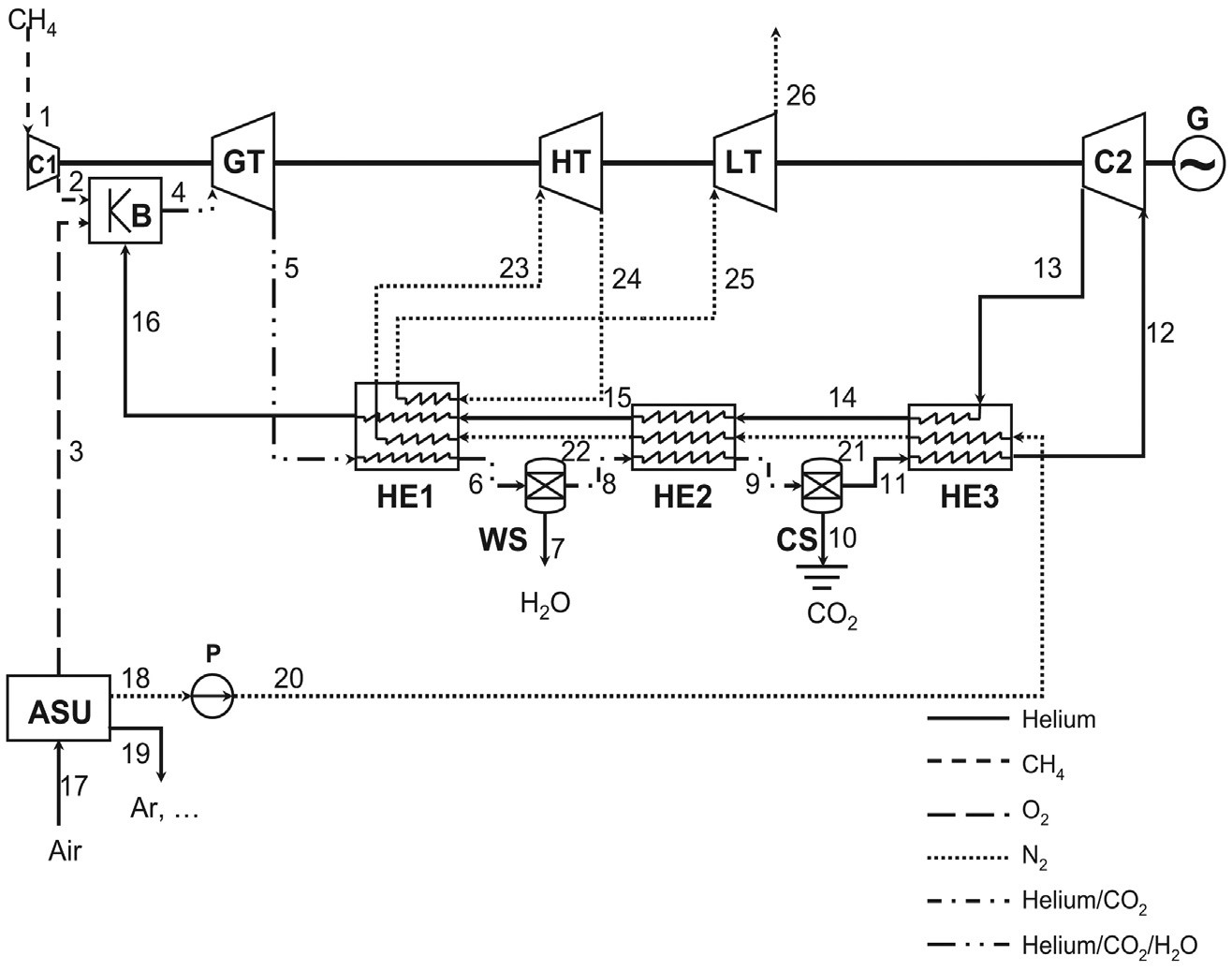
When LAES is combined with a gas turbine-based peaking plant, waste heat from the power generation process can be used, resulting in greater peak-shaving capacity and overall efficiency. Integration can also capture CO2 and convert it to dry ice without sacrificing efficiency. The cycle’s process diagram is shown in the graphic below, and it works as follows. Excess energy produced by the base load is used to power an air separation and liquefaction unit (ASU) that produces oxygen and liquid nitrogen during off-peak hours, while the remainder of the system is turned off. At peak hours, the oxygen and liquid nitrogen produced are kept in a pressurized vessel and a cryogenic tank, respectively, for use in power generation via the high-pressure turbine (HT) and low-pressure turbine (LT), as well as helping combustion in the combustor (B). The liquid nitrogen produced can also be used as a kind of energy storage.
Natural gas is compressed to working pressure in the compressor (C1) during peak hours. The working fluid then reacts with the oxygen in B, resulting in a high-temperature, high-pressure flue gas that contains CO2 and H2O. Natural gas combustion in an oxygen environment can result in a temperature that is too high for the gas turbine (GT) to operate at. Before entering the GT for power generation through a generator, an adequate amount of helium gas is combined with the flue gas to manage the temperature (G).
The helium gas is not burned but rather circulates in the system. The helium-containing flue gas from the GT then passes via heat exchangers 1 (HE1), 2 (HE2), and 3 (HE3) to recover waste heat by passing it to a nitrogen stream from the liquid nitrogen storage tank. Steam is extracted from the flue gas via a condenser (WS), while CO2 is removed in the form of dry ice by a solidification process in the CO2 separator (CS)—the triple point of CO2 is 571.8 kPa (5.718 bar) and 56.6 °C.
As a result, after CO2 removal, the flue gas stream comprises just helium. The helium stream is then cooled further in HE3 and compressed to working pressure in the compressor (C2) before passing through more heat exchange in HE2 and HE1 before returning to the combustor.
LAES with Concentrated Solar Power Plants Integration
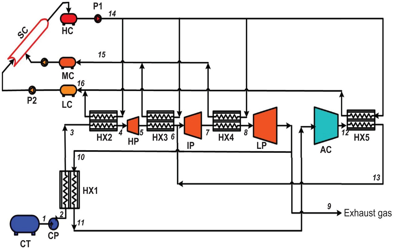
Additional heat sources can improve the LAES system’s roundtrip efficiency. Industrial activities and renewable solar radiation are examples of such heat sources. The utilization of solar heat in large-scale concentrated solar power (CSP) facilities are explored in this subsection. A combined LAES and CSP hybrid power system is depicted in the diagram below. As can be seen, the system lacks a liquefaction mechanism, necessitating the use of an external supply of liquid air/nitrogen. If a large-scale centralized liquefaction facility is located within a reasonable distance, this is feasible.
A direct expansion (open cycle) of liquid nitrogen/air from an elevated pressure and a closed-loop Brayton cycle operating at medium to low pressure make up the system indicated in the diagram. When the Brayton cycle is used instead of the traditional Rankine cycle, the heat transfer process is more efficient and the operating pressure is substantially lower. The expansion takes place in three phases (high-, medium-, and low-pressure turbines), with solar heat employed to superheat the working fluid in between. According to simulation data, such a system generates approximately 30% more power than a system driven solely by solar thermal energy and a system powered solely by LAES energy.
Integration of LAES with Nuclear Power Plants
Nuclear power stations are frequently downregulated to balance demand and supply during off-peak hours, especially when the installations exceed baseload limits. Part-load operations not only raise electricity costs but also jeopardize the safety and longevity of nuclear power facilities. The combination of nuclear power generation and LAES offers a viable approach for effective electrical power output time-shifting. A flow chart of such integration is shown in the diagram below.
A nuclear power plant subsystem and a LAES subsystem make up the integrated system. The integrated system’s nuclear power plant subsystem is similar to a traditional pressurized water power plant. The only variation is that in the secondary loop, there are two three-way valves that allow the working fluid to pass into either the steam turbine or heat exchanger 4 in the LAES subsystem to superheat high-pressure air. In the following diagram, the LAES subsystem comprises an air liquefaction unit on the left and an energy extraction unit on the right bottom.
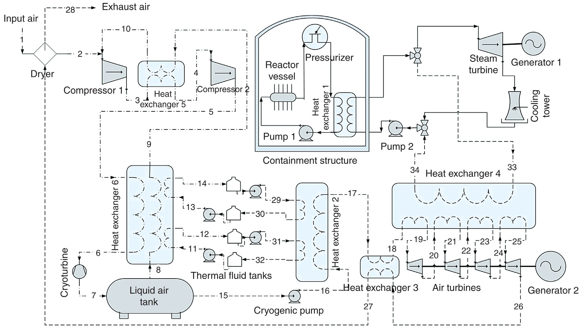
Depending on end-user requests, the integrated system could have three operational modes, which are briefly explained below:
- Energy storage mode: during off-peak hours, when demand is substantially lower than the power plant’s rated output, the power plant runs in a typical mode, driving the steam turbine to produce electricity, with extra power used to drive the air liquefaction unit to produce liquid air.
- Energy release mode: when demand exceeds the plant’s rated power during peak hours, the energy extraction unit is activated to generate additional electricity.
- Conventional mode: When supply and demand are nearly balanced, both the air liquefaction and energy extraction units are turned off, and nuclear power is used to drive a steam turbine to generate electricity in the traditional method.
Integration of LAES with Liquefied Natural Gas Regasification Process
LAES can also be combined with LNG regasification plants, allowing the waste cold to be used in the air liquefaction process. Due to large-volume LNG storage, waste cold in LNG import ports is significant. Normally, LNG is regasified by boiling it with seawater and then burning some natural gas. This wastes the cold stored in LNG and the natural gas that is burnt.
The generated cold air could then be supplied into the air liquefier, potentially reducing its power usage by as much as two-thirds if LAES were collocated at the LNG terminal and air rather than seawater was utilized to provide heat for the LNG regasification process. Several nitrogen liquefiers are currently in operation at LNG import ports in Japan and South Korea, utilizing this refrigeration to reduce power usage. The only obstacle to overcome is lowering the capital cost of such a complex system.
A Comparison Of LAES with Common Energy Storage Technologies from A Technical and Economic Point of View
A quick comparison of LAES and other energy storage systems is presented in this section. The following two subsections will discuss the technical and economic aspects of the comparison.
Technical Comparison
Only pumped hydro storage may be considered a mature technology because it has been used for over a century. Despite the fact that compressed air energy storage technology has been created and is commercially available, it is not widely used. LAES is still in development, along with flow batteries, hydrogen storage, and a variety of other energy storage technologies.
When compared to connected energy storage systems, LAES, like pumped hydro and compressed air energy storage technologies, has a long discharge time (hours). The power discharge rate, on the other hand, is determined by the scalability of the energy storage technologies’ power-regenerating unit. Pumped hydro storage makes use of hydraulic turbines to regenerate electricity and so has the highest power discharge rate (up to several gigawatts). The power rate of compressed air energy storage is in the hundreds of megawatts range due to the utilization of typical gas turbines or steam turbines for power regeneration.
The power rate of a LAES turbine is expected to be slightly lower than compressed air energy storage, but it can still reach hundreds of megawatts. An LAES turbine is similar to a gas turbine but has a lower expansion temperature, so the power rate is expected to be slightly lower than compressed air energy storage. However, because flow batteries and hydrogen storage are difficult to scale, their power output is estimated to be less than a megawatt.
Pumped hydro storage and flow batteries and have a high roundtrip efficiency (65–85%) at the system level. Compressed air energy storage has a roundtrip efficiency of around 40 percent (commercialized and realized) to about 70 percent (still at the theoretical stage). Because of the low efficiency of the air liquefaction process, LAES has a low roundtrip efficiency of around (50–60%). It should be emphasized, however, if waste heat is supplied, the roundtrip efficiency of LAES can be greatly improved.
Hydrogen storage has the largest volumetric energy density, ranging from (500–3000) W h L–1 depending on the storage method (e.g., compressed gas, liquid, physical/chemical adsorption, etc.). However, because hydrogen is a highly flammable gas, it has high technical requirements for storage. At (60–120) W h L–1, the energy storage density of LAES is an order of magnitude lower, but the energy carrier can be kept at ambient pressure. The energy density of pumped hydro storage is (0.5–1.5) W h L–1, while compressed air energy storage and flow batteries are (3–6) W h L–1.
Economic Comparison
The costs per unit amount of power that storage can deliver (dollars per kilowatt) and the costs per unit quantity of energy (dollars per kilowatt-hour) that is stored in the system can be used to make an economic comparison. It’s difficult to assess a technology because costs are influenced by a variety of factors, including system size, location, local labor rates, market volatility, local climate, environmental concerns, and transportation/access challenges. The capital costs given in this section are meant to provide a high-level overview of the challenges, not to be used as cost inputs into a design.
The cost of charging and discharging devices is closely related to the capital costs per unit of power. High power capital costs (>$10,000 kW–1) characterize hydrogen storage. Pumped hydro storage, flow batteries, and compressed air energy storage, and LAES all have around the same power capital costs (between $400 and 2000 kW-1). Because of the effect of discharge durations, capital costs per unit of energy cannot be utilized to accurately measure the economic performance of energy storage devices.
The capital cost of storage systems like a dam for pumped hydro storage and a storage tank for LAES is an alternate measure. Because the energy carriers are either flammable or at high pressure, hydrogen storage and compressed air energy storage are projected to have the greatest storage costs. Due to its low energy density, pumped hydro storage has a cheap cost. Despite the fact that insulation is required, LAES and flow batteries offer the lowest cost.
Mechanical-based systems such as pumped hydro storage, compressed air energy storage, and LAES should have a lifecycle of 20–60 years because they are based on traditional mechanical engineering, and the lifecycle is mostly governed by the lifetime of mechanical components. The lifespan of hydrogen storage and flow batteries, on the other hand, are predicted to be around 5–15 years.
Buy Equipment or Ask for a Service
By using Linquip RFQ Service, you can expect to receive quotations from various suppliers across multiple industries and regions.
Click Here to Request a Quotation From Suppliers and Service Providers
Read More on Linquip

