A hydraulic head or piezometric head is a particular measurement of liquid pressure above a vertical datum. It is regularly measured as a liquid surface altitude, expressed in length units, at the entry (or bottom) of a piezometer. In an aquifer, it can be determined from the depth to water in a piezometric well and provided information of the elevation of the piezometer and depth of the screen. The hydraulic head can likewise be estimated in a column of water employing a standpipe piezometer by measuring the water surface’s height in the tube relevant to a common datum. The hydraulic head can be applied to determine a hydraulic gradient among two or more spots.
“Hydraulic Head” in Fluid Mechanics
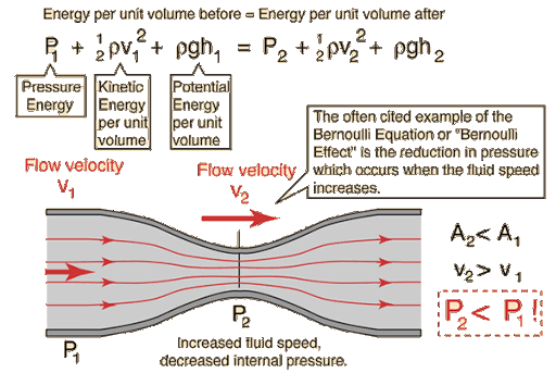
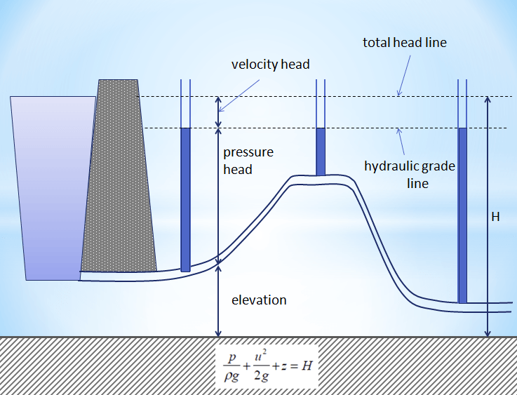
In fluid mechanics, the head is a notion that links the energy in a fluid to the elevation of an equivalent static column of that fluid. From Bernoulli’s principle, the entire energy at a specific point in a fluid is the energy connected with the fluid movement, plus energy from static pressure in the fluid, plus energy from the fluid’s elevation corresponding to an arbitrary datum. Head is represented in units of height such as feet or meters.

The pump static head is the highest height it can present. The pump’s capacity at a certain RPM can be read from its flow vs. height curve.
A general misunderstanding is that the head matches the fluid’s energy per unit weight. As a matter of fact, the term with pressure does not describe any type of energy (for an incompressible fluid, in the Bernoulli equation, this term describes the work of pressure forces). The head is beneficial in designating centrifugal pumps since their pumping properties tend to be independent of the fluid’s density.
There are four types of the head applied to determine the total head in and out of a pump:
- Velocity head is due to the bulk movement of a fluid (kinetic energy).
- Elevation head is due to the weight of the fluid; in other words, the gravitational force acting on a fluid column.
- The pressure head is due to the static pressure, the internal molecular movement of a fluid that applies a force on its container.
- The resistance head is due to the frictional forces acting against a fluid’s movement by the container.

“Hydraulic Head” Components
After free-falling from a specific height, h, in a vacuum from an initial velocity of 0, a mass will have ended at a speed of
v=\sqrt { 2gh }
where g is the gravitational acceleration. Rearranged as a head like the following:
h=\frac { { v }^{ 2 } }{ 2g }
The right-hand term is designated as the velocity head, represented as a length measurement. In a flowing fluid, it means the energy of the fluid due to its bulk movement.
The total hydraulic fluid head is made of pressure head and elevation head. The pressure head is equal to the column gauge pressure of water at the base of the piezometer. The elevation head is the relevant potential energy in terms of elevation. The head equation, which is a simplified form of the Bernoulli Principle for incompressible fluids, can be signified as:
h=\psi +z
where
h is the hydraulic head, also recognized as the piezometric head.
ψ is the pressure head in terms of the height difference of the water column relative to the piezometer bottom, and
z is the height at the piezometer bottom
The pressure head can be written as:
\psi =\frac { P }{ \gamma } =\frac { P }{ \rho g }
where
P is the gauge pressure,
γ is the unit weight of the liquid,
ρ is the density of the liquid, and
g is the gravitational acceleration
Fresh Water Head
The pressure head relies on water density, which can alternate depending on both the temperature and chemical composition of the fluid. This indicates that the hydraulic head estimation is dependent on the water density within the piezometer. If one or more hydraulic head determinations are to be examined, they need to be standardized regularly to their freshwater head, which can be measured as:
{ h }_{ fw }=\psi \frac { \rho }{ { \rho }_{ fw } } +z
where
{ h }_{ fw } is the freshwater head, and { \rho }_{ fw } is the density of fresh waterHydraulic Gradient
The hydraulic gradient is a vector gradient among two or more hydraulic head measurements over the flow path’s length. For groundwater, it is also termed the ‘Darcy slope’, because it defines the quantity of a Darcy flux or discharge. It also has employment in an open-channel flow where it can determine whether a reach is getting or missing energy. A dimensionless hydraulic gradient can be estimated between two spots with known head values as:
i=\frac { dh }{ dl } =\frac { { h }_{ 2 }-{ h }_{ 1 } }{ length }
where
i is the hydraulic gradient,
dh is the difference between two hydraulic heads, and
dl is the flow path length among the two piezometers
The hydraulic gradient can be represented in a vector system, by applying the del operator. This needs a hydraulic head field, which can be substantially achieved only from numerical models, such as MODFLOW for groundwater. In Cartesian coordinates, this can be denoted as:
\triangledown h=\left( \frac { \partial h }{ \partial x } ,\frac { \partial h }{ \partial y } ,\frac { \partial h }{ \partial z } \right) =\frac { \partial h }{ \partial x } i+\frac { \partial h }{ \partial y } j+\frac { \partial h }{ \partial z } k
This vector specifies the groundwater flow direction, where negative values designate flow along the dimension, and zero means ‘no flow’. As with any other physics example, energy must progress from high to low, so the flow is in the negative gradient. This vector can be utilized in conjunction with Darcy’s law and a tensor of hydraulic conductivity to define water flux in three dimensions.
Hydraulic Head in Groundwater
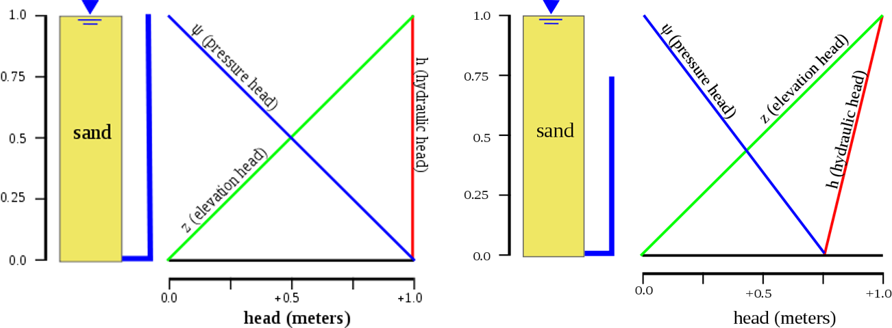
The distribution of hydraulic heads within an aquifer defines where groundwater will proceed. In a hydrostatic example (left figure), where the hydraulic head is fixed, there is no flow. Nevertheless, suppose there is a difference in the hydraulic head from top to bottom due to draining from the bottom (right figure). In that case, the water will flow downward due to the variance in the head, also named the hydraulic gradient.

Atmospheric Pressure
Although it is a convention to apply gauge pressure in the hydraulic head calculation, it is more accurate to use total pressure (gauge pressure + atmospheric pressure), because this is indeed what forces groundwater flow. Regularly detailed observations of barometric pressure are not accessible at each well over time, so this is frequently overlooked.
The effects of atmospheric pressure variations on water levels perceived in wells have been recognized for many years. The effect is a direct one. An increment in atmospheric pressure is an increase in load on the water in the aquifer, increasing the depth of water. Pascal first qualitatively examined these effects in the 17th century. They were more rigorously explained by the soil physicist Edgar Buckingham employing air flow models in 1907.
Head Loss
Energy is dissipated in any real flowing fluid due to friction; turbulence dissipates even more energy for high Reynolds number flows. This dissipation, named head loss, is split into two main categories: “major losses” connected with energy loss per pipe length and “minor losses” related to fittings, bends, valves, etc. The most popular equation applied to calculate major head losses is the Darcy–Weisbach equation:
\frac { \triangledown p }{ L } ={ f }_{ D }.\frac { \rho }{ 2 } .\frac { { \left< v \right> }^{ 2 } }{ D } ,
where the pressure loss per unit length Δp/L is a function of:
ρ, the density of the fluid;
D, the hydraulic diameter of the pipe;
<v>, the mean flow velocity, experimentally measured as the volumetric flow rate per unit cross-sectional area;
{ f }_{ D }, the Darcy friction factor.
For comparatively short pipe systems, with a moderately large number of bends and fittings, minor losses can easily beat major losses. In design, minor losses are regularly estimated from tables utilizing coefficients or a more straightforward and less precise reduction of minor losses to equivalent length of pipe, a method frequently employed for shortcut calculations of pneumatic carrying lines pressure drop.
Buy Equipment or Ask for a Service
By using Linquip RFQ Service, you can expect to receive quotations from various suppliers across multiple industries and regions.
Click Here to Request a Quotation From Suppliers and Service Providers
Read More on Linquip
- Turbo Types: Classifications and Examples
- Velocity Head: All You Should Know About Definition and Importance
- 10 Parts of Hydraulic Pump + PDF & Function
- Top Best Hydraulic Equipment Manufacturers in USA and World
- Difference Between Hydraulics and Pneumatics
- 4 Types of Hydraulic Valves & Their Working Principles


