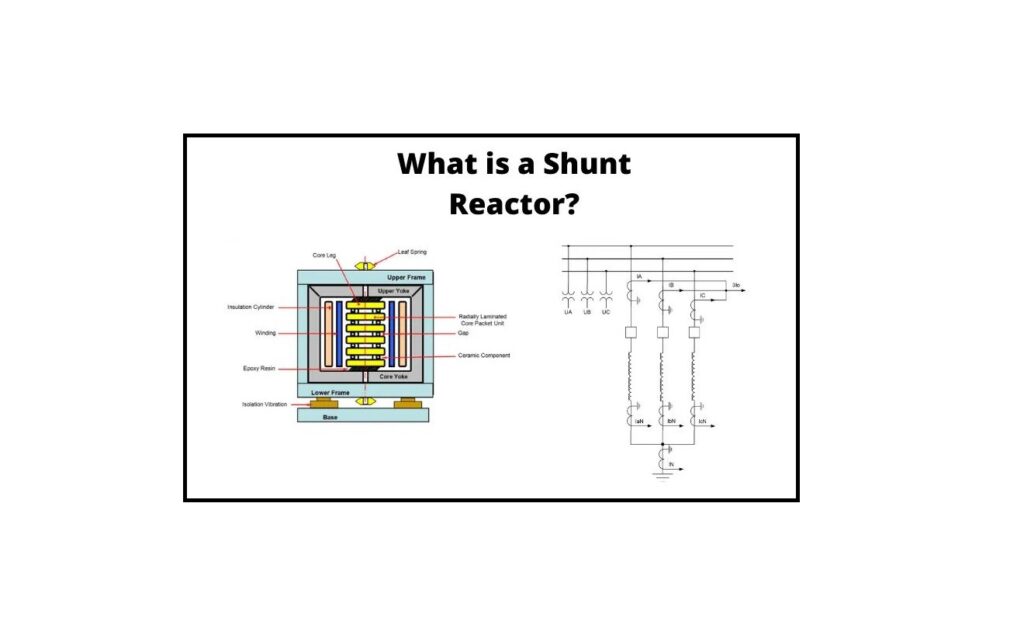
What is a Shunt Reactor, and how does it work? A shunt reactor is a reactive power absorber that improves the system’s energy efficiency. In long high-voltage transmission lines and cable networks, it is the most compact device for reactive power adjustment. The shunt reactor can be connected directly to the power line or a three-winding transformer’s tertiary winding. In high-voltage energy transmission systems, shunt reactors are employed to keep the voltage stable during load changes. Traditional shunt reactors have a fixed rating and are either permanently connected to the power line or switched in and out depending on the demand.
What is a Shunt Reactor?
In high-voltage power transmission networks, a shunt reactor is one type of electrical device that is used to maintain the voltage across load differences. A conventional shunt reactor’s rating is fixed, and it is always linked to the transmission line based on the load.
The working concept of a shunt reactor is that it acts as a reactive power absorber in an energy system, increasing the efficiency of the system. It’s a small gadget that’s utilized in high-voltage transmission lines and cable systems to compensate for reactive power. This can be connected directly to the power line or the tertiary winding of a 3-winding transformer. A circuit breaker is employed to permanently connect or switch this shunt reactor.
It must be able to operate at the maximum continuous voltage possible. For the 400 kV system, for example, the typical power frequency difference can be 5% higher than the rated voltage without exceeding 150oC for any element of the shunt reactor. Core losses can happen when the reactor is operating normally. As a result, when designing, special attention must be paid to minimizing these losses.
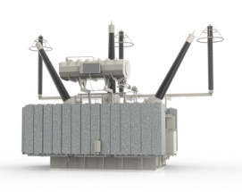
Shunt reactors are widely employed in high-voltage energy transmission networks to manage voltage overload differences. These reactors will run to offer reactive power compensation based on voltage requirements.
Construction of a Shunt Reactor
This reactor is mostly used to compensate for the transmission line’s capacitive reactive power. The shunt reactor’s design may differ from one designer to the next.
Shunt reactors and power transformers are identical, with the exception that each phase has only one winding. In the star model, the windings of these can be joined by reaching the neutral point (YN). The installation of an earthing system throughout the power transformer’s tertiary winding can be accomplished by connecting the neutral point. There are two sorts of these reactors: conservator/dry type and oil-immersed type.
The precautions and accessories utilized in this reactor are identical to those found in power transformers. Especially in an oil-immersed type reactor, where the oil pressure in the relief valve as well as the air breather must be emphasized. Shunt reactors are similar to power transformers, except they only have one winding per phase, as previously stated.
Those three windings are connected by a star to the neutral point (YN). The neutral point is either connected to the installation’s earthing system via the tertiary winding of a power transformer or directly. A typical shunt reactor connection diagram is shown in the figure below.
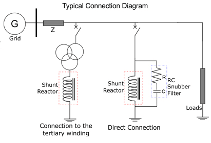
Built-in protections are similar to those found in power transformers (Buchholz relay and oil pressure and temperature sensors for oil-immersed type; windings temperature probes for dry type). Accessories are comparable to those used in power transformers, particularly those that are oil-immersed, in which the oil pressure relief valve and the air breather must be noted. Visit here to know the construction and principle of shunt reactors in detail.
Types of Shunt Reactor
These are divided into two categories based on their construction: dry and oil-immersed.
Dry Type
A Dry-type shunt reactor is typically limited to a voltage of 34.5 kV. It is usually applied to the third winding (tertiary) of a transformer and connected to the compensated transmission line. These reactors are air-cored, open to the atmosphere, and suitable for indoor or outdoor use. The natural convection of ambient air is utilized to cool the unit in most cases, with windings arranged to enable airflow between turns and layers.
These twists and layers are mechanically supported by bracing elements; otherwise, different materials such as glass polyester, concrete, and ceramics are used as supports. Reactors can be built as single-phase units and set over insulating pedestals/base insulators to provide insulation to the ground and support the reactor.
This type of reactor has no shielding but produces a high-intensity external magnetic field once it is turned on. It’s important to mark the clearances, as well as the reactor unit layout, station construction, mounting pad, and any metal areas in the reactor’s vicinity, with care.
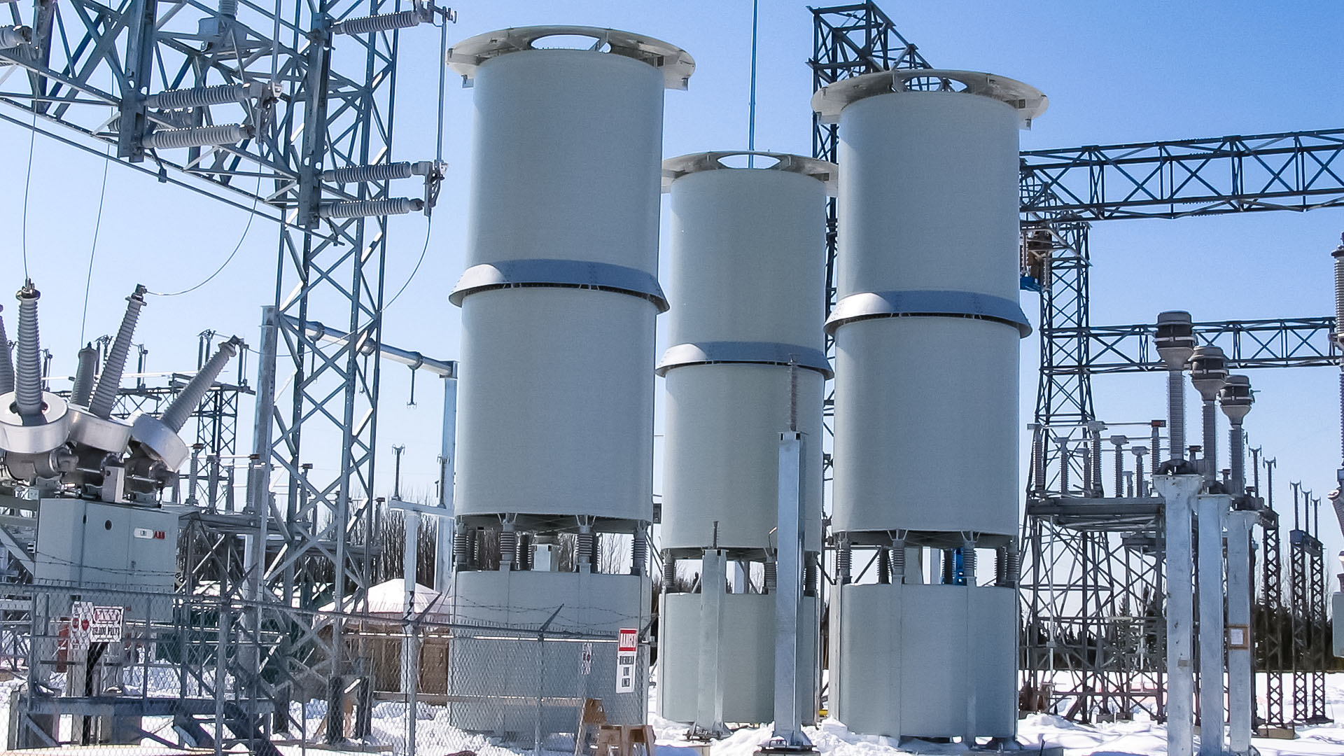
A closed metallic loop in the reactor’s close surroundings will generate heat, losses, and arcing at joints; hence, it is critical to keep sufficient distances from these loops. When it is not possible to build dry-type units in an equilateral-triangle arrangement that is isolated from external magnetic forces, shielding is required.
Dry-type reactors have some advantages over oil-immersed types, such as lower weight, lower cost, lower losses, and lower maintenance. The main disadvantages are voltage rating limitations and a high-intensity external magnetic field. The reactor does not have an iron core when it is turned on, and there is no magnetizing inrush current.
Oil-Immersed Type
These reactors are available in two design configurations: coreless and gapped iron-core. The parallel arrangement of the reactor inductance and line capacitance in these two designs results in long-term steady currents with low-frequency throughout de-energizing. However, when compared to the coreless kind, the gapped iron-core design has a more severe energizing inrush.
A magnetic shield surrounds the loop in most coreless shunt reactor designs to keep the flux in the reactor tank. In most cases, the steel core leg creates a magnetic flux lane by connecting the loop of a power transformer to insulating support structures. As a result, this type of design will produce a voltage-linear inductor.
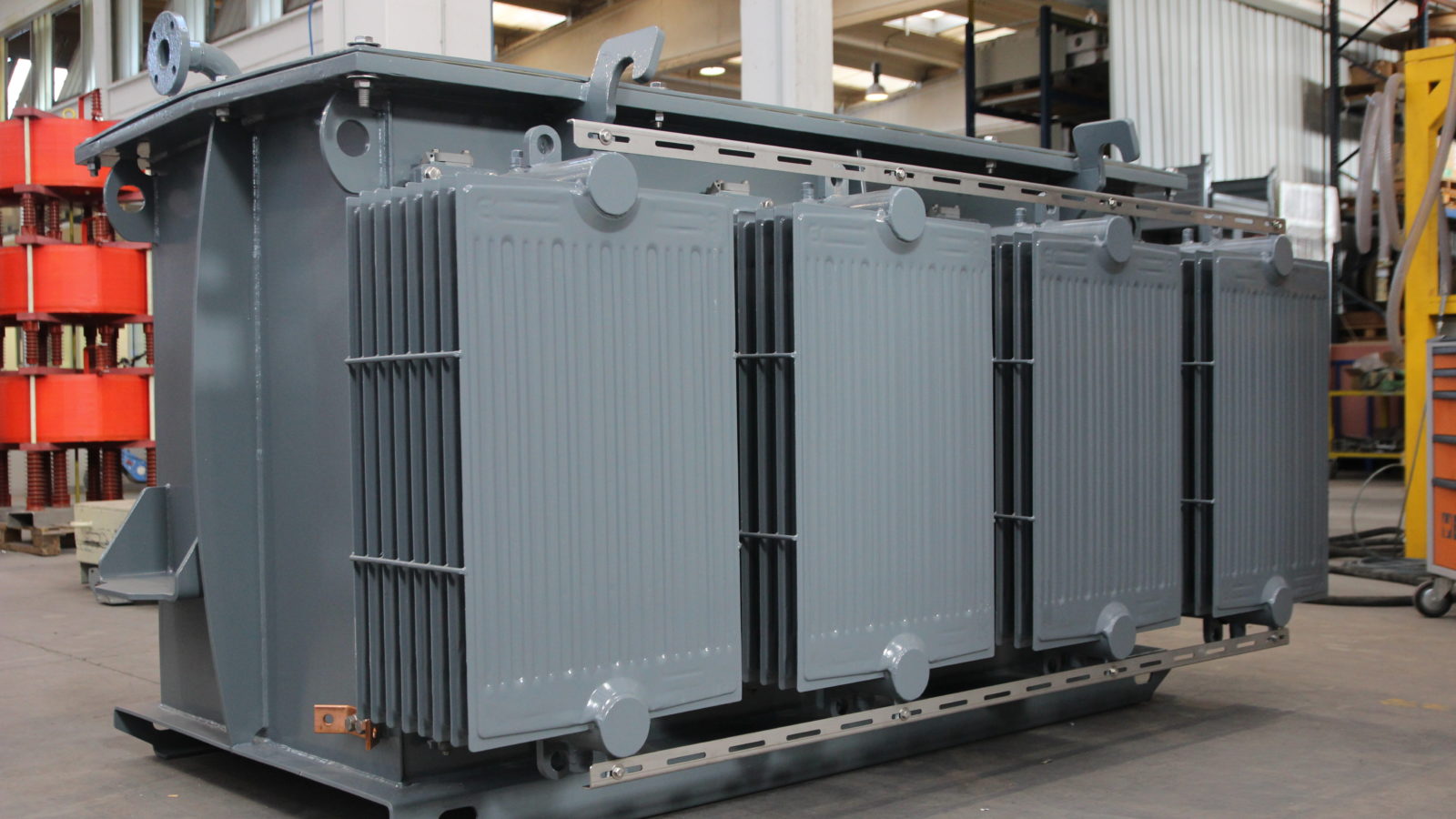
These reactors are constructed as single-phase or three-phase devices, and their exterior appearance is quite similar to that of standard power transformers. They are primarily intended for forced or self-cooling applications.
Difference between Shunt Reactor and Power Transformer
Both the shunt reactor and the power transformer are built similarly, but they have some significant differences based on their properties. The fundamental differences between a shunt reactor and a power transformer are stated in the following:
- A shunt reactor has a single winding, but a power transformer has three.
- To improve the system’s efficiency, this sort of reactor uses reactive power. The power transformer is used to adjust the voltage in a step-up or step-down manner.
- Because there are no other windings in this reactor, primary ampere-turns like AT are equivalent to minor ampere-turns. The major ampere turn, AT, in a power transformer, is the sum of moving AT and minor AT.
- To prevent hysteresis loss, a shunt reactor can be designed without using an iron core. An iron core can be used in the design of a power transformer.
- There are two types of shunt reactors: dry and oil-immersed. Power transformers come in a variety of configurations, including autotransformer, polyphase, leakage, and resonant.
- The magnetizing current in a shunt reactor is very high. Magnetizing current is lower than that of a shunt reactor in a power transformer.
- The MVA rating of a shunt reactor. The power transformer has a kVA rating.
- Shunt reactors are utilized in high-voltage systems and cable networks. The voltage level is transmitted using a power transformer.
Measurement of Losses in Shunt Reactor
Losses in shunt reactors should be determined at both rated voltage and frequency. However, assembling a high test voltage during the measurement of losses for a shunt reactor with an extraordinarily high voltage type may be difficult. As a result, complications can be minimized by detecting the shunt reactor’s measurement losses at a voltage lower than the reactor’s system voltage.
The observed loss can then be multiplied by the square of the proportion of the rated current and the reactor current to obtain the loss at the rated voltage and decreased test voltage. When the power factor of the shunt reactor is low, conventional wattmeter loss measurements are unreliable; instead, a bridge technique for measurement may be used for better precision.
The measurement losses in different parts of the shunt reactor cannot be separated using this test. To avoid the test correction resulting in a reference temperature, it is better to get the measurement once the normal temperature of the winding is identical to the reference temperature.
Why Use Shunt Reactor?
Aside from resistance, actual electrical circuits contain an inductive and/or capacitive component, which causes a phase shift between voltage and current, as shown in the Figure below, and reactive power (unit: VA) to flow through the circuit.
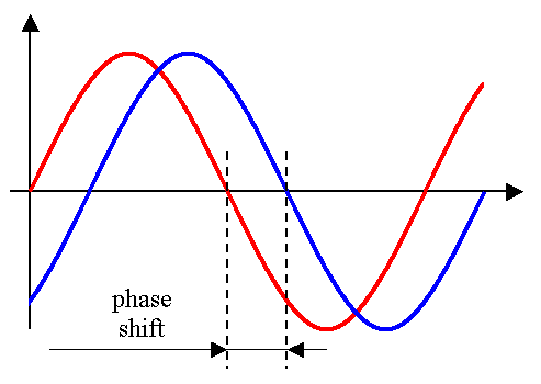
Current will be lagging if inductance (XL is 2πfL or jωL) prevails, and reactive power is referred to as inductive power.
Where XL (Ω – ohm) is the inductive reactance, f (Hz – hertz) is the frequency, L (H – henry) is the inductance, and ω is the rotational speed (rad/s or rpm – revolutions per minute or radians per second).
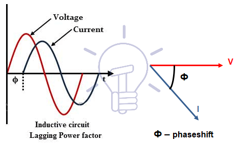
Long overhead lines are an example of this. The result of lagging currents (low power factor) is widely understood, as is the method for increasing power factor (installation capacitor banks).
If the capacitance is prominent (XC = 1/2πfC = j/ωC), as it is in extensive underground cable networks. So, the current will be the driving force, while reactive power will be referred to as capacitive power.
Where XC (Ω– ohm) is the capacitive reactance and C (F – farad) is the capacitance.
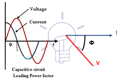
This condition is also dangerous to power transformers, particularly generators.
Ferro resonance, an over-voltage phenomenon that can damage transformers and/or surge arresters, can occur in power transformers. Generators are called upon to produce excessive capacitive power in weak networks that operate as islands and are not connected to a larger, more complicated electrical network, causing overheating and generator breakdown and reducing the equipment’s usable life.
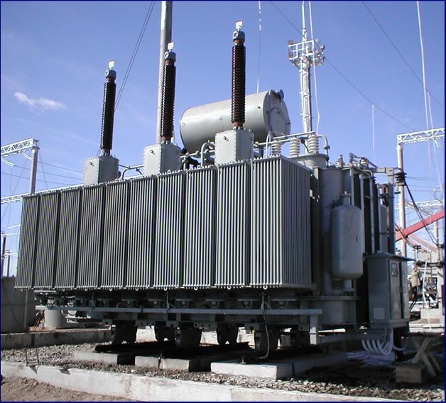
Shunt reactors, equipment that must fit with IEC Standard 60076-7, of which an example is illustrated in Figure below, must be used to compensate for the high reactive power.
Applications of Shunt Reactor
The following are some of the applications of shunt reactors:
Because it absorbs and compensates for reactive power in transmission lines and cables, it is utilized to improve the efficiency of power and energy systems.
It acts as a reactive power absorber, increasing the system’s energy efficiency.
It can be used in a variety of systems, including HV and EHV.
The variable shunt reactor is used to dynamically optimize the current network state as well as the voltage in the network.
It is utilized to improve network stability as well as provide continuous voltage regulation in low-load or no-load operation of the lines.
These are utilized to improve the quality of the power as well as the voltage stability.
Summary
This is all about a general overview of the shunt reactor, including its construction, operation, and applications. It’s similar to a power transformer, except instead of having multiple windings for each phase, it only has one. These reactors are primarily utilized to increase the system’s power and efficiency by absorbing and balancing the reactive power within as well as transmission lines with high voltage. Shunt reactors can be connected directly to the tertiary winding or the power line of a three-winding transformer. Now, we have a question for you: what are the benefits of using a shunt reactor? Share your comments with us.
Buy Equipment or Ask for a Service
By using Linquip RFQ Service, you can expect to receive quotations from various suppliers across multiple industries and regions.
Click Here to Request a Quotation From Suppliers and Service Providers
Read More on Linquip

