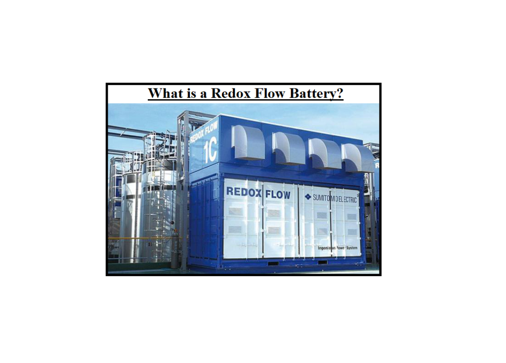
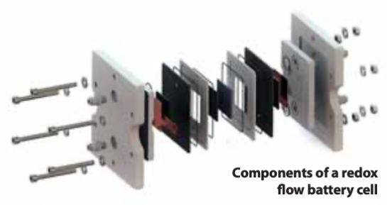
Redox Flow Battery- Redox flow batteries are a form of battery that is distinct from others. It consists of two electrolyte-fluid-filled tanks and one electrolyte-fluid-filled stack. Several stack cells, each with a frame, bipolar plate, and membrane make up the stack. The number and size of stack cells are determined by the required power output. Also, the capacity of a battery is determined by the size of the tanks and the fluid in the two tanks serves as a cathode (positive electrolyte) and anode (negative electrolyte) (negative electrolyte) like a standard battery.
What is a Redox Flow Battery?
When defining what a redox flow battery is, we must first define the redox term.
What Does Redox Mean?
In redox flow, the term redox refers to redox-reaction, which is the description of a chemical’s change in oxidation level: reduction and oxidation. Electrons are transported from one element to another in this process.
Definition of a Redox Flow Battery
One type of electrochemical energy storage system is the Redox Flow Battery (RFB). As explained before, the term “redox” refers to the RFB’s use of chemical reduction and oxidation reactions to store energy in liquid electrolyte solutions that flow through a battery of electrochemical cells during charge and discharge.
During discharge, an electron is released from a high chemical potential state on the negative or anode side of the battery via an oxidation reaction. To perform a significant function, the electron travels through an external circuit. Finally, on the positive or cathode side of the battery, the electron is accepted via a reduction reaction at a lower chemical potential state. During charging, the direction of the current and the chemical processes are reversed.
The electromotive force (EMFor voltage) generated in each cell of the battery is determined by the total difference in chemical potential between the chemical states of the active materials on the two sides of the battery. The RFB’s voltage is dependent on the chemical species involved in the reactions as well as the number of cells arranged in series.
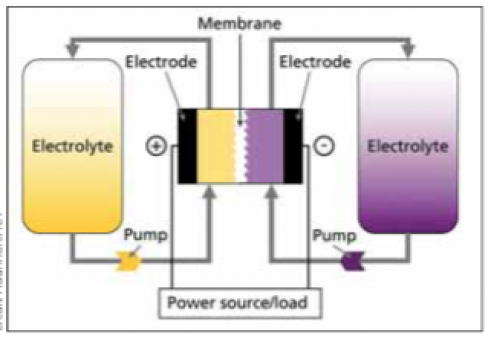
The number of atoms or molecules of the active chemical species that are reacted within the cells as a function of time determines the current generated by the battery. The total current and total voltage created in the electrochemical cells are multiplied by the RFB’s power output. The total number of active chemical species available in the volume of electrolyte solution present in the system determines the quantity of energy stored in the RFB. If you want to explore more about redox flow batteries, visit here.
How Redox Flow Batteries Work
When compared to other electrochemical storage devices, a significant characteristic of RFBs is the separation of power and energy. The system energy is stored in the volume of electrolyte, which can simply and economically range from kilowatt-hours to tens of megawatt-hours, depending on the size of the storage tanks, as stated above.
The size of the stack of electrochemical cells determines the system’s power capability. At any given time, the amount of electrolyte flowing in the electrochemical stack is usually less than a few percent of the total amount of electrolyte present (for energy ratings corresponding to two to eight hours of discharge at rated power).
During a fault situation, flow can be quickly stopped. As a result, in the case of RFBs, system sensitivity to uncontrolled energy release is limited to a few percent of the total energy stored due to system architecture. This differs from packaged, integrated cell storage systems (lead-acid, NAS, Li-Ion), in which the entire system’s energy is connected and accessible for discharge at all times.
The separation of power and energy allows for greater design flexibility when using RFBs. The power capability (stack size) can be adapted to the load or generating equipment directly. The storage capacity (the size of the storage tanks) can be customized to the unique application’s energy storage requirements. RFBs can then provide an efficient storage system for each application at a low cost.
Integrated cells, on the other hand, have a set power-to-energy ratio at the time of design and manufacture. The number of alternative cell designs that can be produced due to economies of scale in cell production is limited. As a result, storage applications with integrated cells typically have an excess of energy or power capabilities.
True redox flow batteries, in which all of the chemical species active in energy storage are entirely dissolved in solution at all times, and hybrid redox flow batteries, in which at least one chemical specie is deposited as a solid in the electrochemical cells during charging, are the two types of RFBs. The vanadium-vanadium and iron-chromium systems are examples of true RFBs. Zinc-bromine and zinc-chlorine systems are examples of hybrid RFBs.
Complete Separation of Power and Energy
True RFBs obtain complete separation of power and energy, as well as all of the benefits. Because energy is stored in the metal that is plated in the electrochemical stack during charge, complete separation of power and energy is not achieved in hybrid RFBs. The differentiation between hybrid RFB and integrated cell architectures is only partially achieved because a bigger energy storage capacity necessitates a larger stack.
Finally, RFBs are ideally suited to applications requiring power in the tens of kilowatts to tens of megawatts, as well as energy storage in the 500 kilowatt-hours to hundreds of megawatt-hours range. Because storage tanks and flow controls are simple and inexpensive to scale, and electrochemical stacks can include repeat units with power ratings in the tens to hundreds of kilowatts, RFBs may be the most cost-effective option in this range.
When contrasted to integrated cell architectures of electrochemical storage, redox flow batteries have one major architectural drawback. Particularly in high-power, short-duration applications, RFBs have lower volumetric energy densities than integrated cell designs. Because the system’s electrolyte flow distribution and control components are really not employed to store energy, the system is not as compact as other technologies with a similar output. Despite this, RFBs with system footprints less than the EPRI substation objective of 500 ft2 / MWh are available.
Redox flow batteries are a cost-effective and low-risk way to store electrical energy at the grid-scale. Other electrochemical techniques of storing electrical energy, such as redox flow batteries, offer less flexibility in setting power and energy ratings for a given application. With power ratings ranging from tens of kW to tens of MW and storage durations ranging from two to ten hours, redox flow batteries are ideal for energy storage applications.
Redox Flow Battery Principles
While charging, all electrochemical energy storage systems convert electrical energy to chemical energy, and when discharging, the process is reversed. Conversion and storage occur in closed cells in traditional batteries. Redox flow batteries, on the other hand, separate energy conversion and storage.
The energy storage material in redox flow batteries is transferred by an energy converter, unlike in ordinary batteries. This necessitates the use of a flowable energy storage element. This structure is comparable to that of fuel cells, in which charging and discharging processes can occur in the same cell in redox flow batteries. As a result, redox flow batteries have the unique characteristic of being able to scale energy and power individually.
The cell size or the number of cells is determined by the power and the energy is governed by the amount of energy storage medium. As a result, redox flow batteries are better suited to specific applications than other technologies. In theory, there is no limit to the quantity of energy that may be stored, and specific investment costs commonly reduce as the energy/power ratio rises, as the energy storage medium is typically inexpensive.
The general running concept of redox flow batteries is illustrated in the figure below. An electrochemical cell that is divided into two half cells is used to convert energy. An ion-permeable membrane or separator separates the half cells from one another, allowing the liquids of the half cells to mix as little as possible. The separator maintains a charge balance between the positive and negative half cells, ideally avoiding direct contact between the negative and positive active materials. However, because separators are imperfect, some active material cross-over always occurs, resulting in the self-discharge effect.
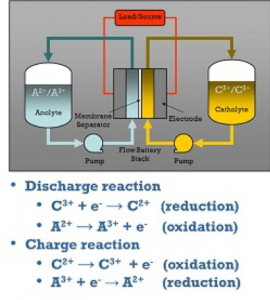
There is always one positive and one negative half-cell in a single cell. The electrodes of the half-cells are where the electrochemical reactions for charging and discharging take place. The electrodes are the ionic and electronic conductors’ phase transitions. The electrodes in redox flow batteries should not participate in the energy conversion reactions and should not induce any additional side reactions (e.g. undesirable gas formation). Carbon electrodes are used in the majority of redox flow batteries.
The cell voltage is the difference between the positive and negative electrode voltages in aqueous systems, and it ranges between 0.5V and 1.6V. Ions are oxidized at the positive electrode (electron release) and reduced at the negative electrode during the charging process (electron uptake). This indicates that electrons pass from the positive electrode’s active material to the negative electrode’s active material. The process is reversed while discharging, and the energy is released. Redox pairs, or chemical molecules that can receive and release electrons, are active materials.
The energy storage medium in redox flow batteries is commonly referred to as an electrolyte. However, unlike hydrogen, some redox flow batteries use a gas that is not an electrolyte (e.g. H/Br-RFB). Water limits apply to aqueous energy storage media from redox flow batteries, just as they do to all other aqueous batteries. Water is dissolved into its parts, hydrogen, and oxygen, when too high voltages, or more accurately too high or too low half-cell potentials, are applied.
The creation of hydrogen, for instance, is frequently present as a minor but unwanted side reaction, resulting in a charge carrier imbalance between the positive and negative half-cells and a gradual loss of capacity. The reaction products that would ordinarily remain in the half-cell can be moved out of the cell and stored in separate tanks due to the flowability of the energy storage medium, allowing for a larger capacity than conventional batteries.
Types of Redox Flow Battery
Different types of redox flow batteries are present below based on their structure and principle.
Hybrid Redox Flow Battery
There are usually no phase transitions with solid active materials in redox flow batteries, unlike other batteries. Because no lattice structures must be rebuilt each time the battery is charged or discharged, and all materials are in solution, this can considerably extend battery life. The vanadium redox flow battery is the most well-known example of a redox flow battery today.
Flow batteries, on the other hand, have materials deposited and dissolved at one or both electrodes. The zinc/bromine redox flow battery, patented by Charles Bradley in 1885, is a good example. Hybrid redox flow batteries are the name for these types of batteries. Power and energy are not separately scalable, unlike redox flow batteries, because the amount of potential solids deposition is restricted by the cell design.
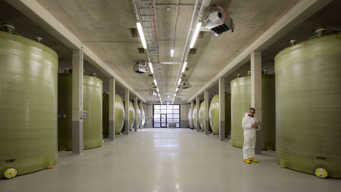
Like conventional redox flow batteries, hybrid redox flow batteries have two electrolyte circuits, but too much active material can cause a thick layer of solids in the half-cell, clogging the fluidic system, or so-called dendrites, which are uneven deposits that can cause short circuits through the separator.
The power density of the half cells, like that of all other batteries, falls as the layer thickness of the half cells increases. As a result, the deposition volume and hence the layer thickness are optimized in terms of power density, resulting in storage times of around 4-8 hours. The low price of the active ingredients, zinc and bromine, as well as the high energy density of roughly 70-80Wh/liter, are benefits of the Zn/Br redox flow battery.
The usage of bromine and the relatively limited cycle life of several thousand charging and discharging cycles are the main disadvantages. When the positive electrode of the battery is charged, the elementary bromine is generated. Organic complexing agents are added to the energy storage medium to bind the bromine and prevent it from escaping, reducing the risk potential and self-discharge. The complexing agent is relatively costly, and it is being studied to reduce battery costs.
From an electrochemical aspect, the employed redox pair Br/Br- has a very fast reaction speed and is suitable for batteries. Exxon and GE initiated relevant commercialization efforts in the United States in the 1970s, which resulted in stack concepts, materials, and production technologies that are still important today.
Later, beginning in the 1980s, commercialization efforts were mostly led by ZBB Corp. of Australia, which produced modular multi-megawatt battery systems before terminating operations a few years ago. Electric vehicle improvements were made in the 1980s, especially by the Austrian companies SEA and Powercell. Experiments with the batteries were conducted in a variety of commercial vehicles including buses. The EV Division of the 1994 and 1995 World Clean Air Car Rallies in California was won by a vehicle with a Powercell battery. Only one company now sells Zn/Br-RFBs.
Vanadium Redox Flow Battery
The vanadium redox flow battery (VRFB) is without doubt the most researched and widely used redox flow battery today. Almost every aspect of the vanadium redox flow battery is covered in numerous patents and papers. The VRFB exclusively uses vanadium in three different oxidation states as an active material. At the positive electrode, the redox pair VO2+/VO2+, and at the negative electrode, the redox pair V2+/V3+.
Because the positive and negative electrolytes use the same ions, relatively high concentrations of active material are possible. This permits the traditional VRFB to hold up to 1.8mol/L vanadium in solution, resulting in a maximum energy density of up to 38Wh/L. Vanadium is a moderately common metal that is enhanced as a by-product of fossil fuel combustion. Its primary use is as an alloying metal in the manufacturing of steel. Since no complex phase transitions or new phase build-ups are required when employing vanadium ions in solution, potentially very long cycle lifetimes can be attained.
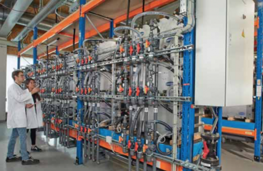
Another advantage is that the batteries are easily recyclable. Because the liquid electrolyte has a high amount of vanadium, it may readily be reintegrated into process chains and the existing value utilized. The energy storage solution is predominantly vanadium sulfate in a diluted (2mol/L) sulfuric acid with a low phosphoric acid concentration and is thus broadly comparable to the acid used in lead/acid batteries. The concentration of pentavalent VO2+ limits the energy density.
Unfortunately, pentavalent vanadium ions tend to react with one another, resulting in the production of bigger molecules that solidify and cause damage to the system. The reaction is influenced by temperature and VO2+ concentration (state of charge), but it is also influenced by proton concentration. The stability of VO2+ is increased by increasing the acid content, but the solubility of the V(II), V(III), and V(IV) sulfates is reduced.
To achieve an appropriate working temperature range, the vanadium and total sulfate concentrations are set at roughly 1.8mol/L and 4.2mol/L, respectively. The tendency for solids to develop in the positive half-cell rises with a high state of charge and rising temperature, which is why the electrolyte temperature is normally limited to a maximum of 40°C. A lower limit of 10°C is usually recommended to reduce the risk of other species precipitating at low temperatures. The SOC limits can also be changed to accommodate temperatures outside of this range.
VRFBs, like all other RFBs, have a battery management system. A battery management system guarantees that the battery operates in the best and safest possible conditions. A heat management system is frequently implemented to prevent excessively high or low temperatures. The classic VRFB has undergone a number of revisions. The goals of employing the rapid redox pair Br2/Br- were to increase energy density and temperature stability, as well as perhaps increase energy efficiency.
The vanadium ions are dissolved in a mixture of hydrochloric acid and sulfuric acid created at the Pacific North West National Laboratory (PNNL). Temperature stability and energy density are increased by up to 50Wh/L. The internal generation of chlorine gas in the system, which places a higher strain on material stability, is a disadvantage. Vanadium/oxygen cells, also known as Gen 4, generate energy by oxidizing vanadium ions with oxygen (for example, from the air) during discharge.
In the charging process, the procedure is reversed. It is theoretically possible to attain an energy density of up to 150Wh/L. VRFBs today range in size from a few kW/kWh to hundreds of MW/MWh. The uses range from personal storage to industrial plants serving as huge grid storage units. VRFBs are now available from a variety of manufacturers in a range of sizes.
Energy Storage and Different Technologies of a Redox Flow Battery
Energy storage is becoming more important in our daily lives, and it will become even more in the near future. We are growing increasingly reliant on batteries, whether to power our cars and phones, to use energy generated by renewable energy sources on a windless, cloudy day, or for server backup. However, we have learned to assume that batteries will wear out and need to be renewed every few years, with the old batteries being discarded.
- Should it be this way?
The issue arises from the fact that ordinary batteries degrade with time, regardless of whether they are utilized or not. They only have a certain number of charge/discharge cycles before they must be discarded.
You can solve this problem with redox flow batteries. The technology enables more charge/discharge cycles, and the life expectancy of a battery solution will be comparable to that of a PV system. The electrolyte will not deteriorate with redox flow technology, and the battery is 100% recyclable.
Redox Flow Batteries for Renewable Energy Storage
As non-lithium (and non-pumped hydro) energy storage becomes a more important aspect of a renewables-based system, interest in and discussion of non-lithium (and non-pumped hydro) technology grows. With a team of experts, CENELEST, a joint research project between the Fraunhofer Institute for Chemical Technologies and the University of New South Wales, explores redox flow batteries.
The growth of renewable energy sources such as solar and wind energy has advanced dramatically in the previous 15 years. Simultaneously, production and installation costs, particularly for PV systems, have decreased dramatically, making this energy source, depending on location, one of the cheapest and cleanest sources of electricity. As the amount of fluctuating renewable energy in an electrical grid grows, the demand for compensating options for times when renewable energy is unavailable increases.
Electrochemical energy storage, such as lithium-ion, lead-acid, sodium-sulfur, or redox-flow batteries, is one option. Combinations of hydrogen electrolysis and fuel cells are also possible. Batteries can be scaled from a few kW/kWh for residential storage to systems of several MW/MWh for grid storage and can be altered in a flexible and decentralized manner based on the respective requirements.
The physical/chemical features of different types of electrochemical energy storage systems determine the cost of the system. It’s worth noting that the lifetime cost of a storage system (Levelized Cost of Storage – LCOS) is a significant consideration when choosing the best system for a given application. Lead-acid batteries, for example, have cheaper initial costs than all other technologies, but their service life is quite short.
Low levelized cost of storage is achieved by technologies with identical investment prices over longer lifetimes, but other aspects like recycling, energy efficiency, and maintenance costs must be evaluated. An ideal system would be a battery with high efficiency, little recycling effort, minimal investment and maintenance expenses, and tremendous scalability to meet the application’s requirements.
There are three types of storage time needs in electrical networks: short-term storage, medium-term storage, and long-term storage. Physical storage devices, such as capacitors, are better suited to short-term storage. Batteries can be used for tasks that last anything from a few minutes to several hours. Furthermore, mass storage techniques like electrochemical hydrogen generation (power-to-gas) are well-suited to long-term storage for several weeks.
Buy Equipment or Ask for a Service
By using Linquip RFQ Service, you can expect to receive quotations from various suppliers across multiple industries and regions.
Click Here to Request a Quotation From Suppliers and Service Provider
Read More In Linquip

