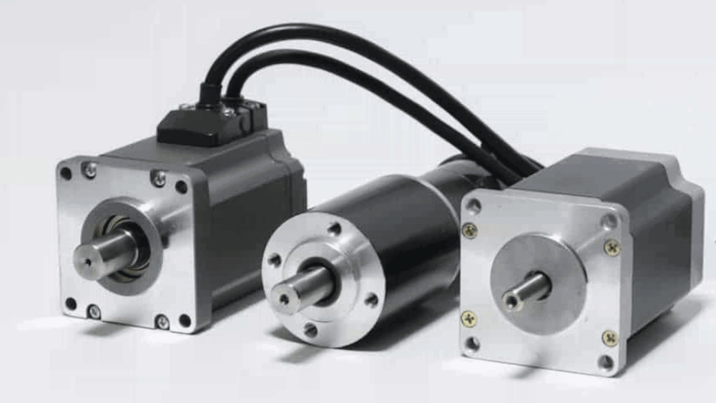
In our daily lives, we come across a variety of battery-powered electrical gadgets that transform electrical energy into mechanical energy, such as hairdryers, toy vehicles, tiny fans, trimmers, and so on. The electrical component responsible for this action is a Direct Current (DC) motor present inside those gadgets.
A DC motor is a type of electric machine that converts electrical energy into mechanical energy. They take electrical power through direct current and convert this energy into mechanical rotation. Today, DC motors have become an integral part of the industrial sector and are used for various applications, such as electric vehicle propulsion, elevators, cranes, and steel rolling mill drives. In this article, we will discuss the working principle of DC motor. Follow this new blog in Linquip to find out more.
DC Motor Components
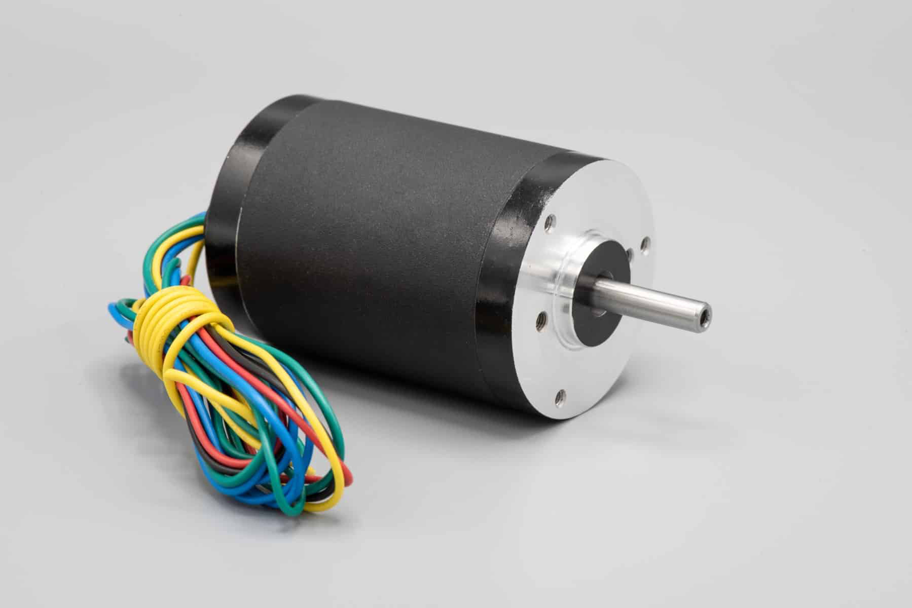
To understand the working principle of DC motor, let’s first look at the components used in its construction. A DC motor usually looks like a cylindrical device with a shaft extending out of it that rotates on applying DC. This action is carried out by arranging the following components in a particular manner.
Stator
A stator, or a steel yoke, is a cylindrical metal casing inside which all the other elements of a DC motor are placed. One face of the stator contains a vertical shaft coming out of it, while the other face has the two terminals to which the DC power supply is connected.
Magnets
There are two stationary permanent magnets installed inside the stator of a DC motor. They act as the north and south poles of a magnet by setting up a horizontal magnetic field across them.
Armature
In electrical engineering, the term armature refers to a structure of rotating coils under the influence of electromagnetic force. In a DC motor, an armature is composed of a rotor placed between the two magnets. A rotor is a structure of laminated discs wrapped around by a conducting field coil. The shaft pointing out of the motor passes along the axis of the armature and rotates along with it.
Field Coil
The field coil or field winding in a DC motor is a coil of copper wires that replaces the permanent magnets attached to the inside walls of the stator. When DC from a battery is passed through this coil, it forms an electromagnet whose polarity can be controlled, setting up a desired magnetic field.
Commutator
A commutator is a hollow cylindrical piece segmented at many spots to reverse the polarity of the electromagnetic armature coil inside the DC motor. It is a critical part of a motor to work on a DC power supply. It sits at the end of the armature around the shaft. The ends of the armature coil are connected to the commutator, while all other parts, except brushes, are electrically isolated from it.
Brushes
The brushes in a DC motor are the components that connect the static terminals to the rotating parts of the motor. They are usually made of carbon graphite since it is a great conductor of electricity and have excellent lubricant properties. The commutator is positioned between the two brushes, which are further connected to the motor’s terminals, completing the circuit with the DC power source.
Read More on Linquip
- Working Principle of Stepper Motor: The Only Guide You’ll Ever Need
- Everything You Need to Know About Working Principle of AC Motor
- The Only Guide You’ll Ever Need For The Working Principle of Induction Motor
- DC Motor Parts, Structure, Design and Advantages
Working Principle Of DC Motor
A DC motor works on the principle that whenever a current-carrying conductor is placed inside a magnetic field, it experiences a magnetic force whose direction is given by Fleming’s Left-hand Rule. In other words, the DC motor spins due to the interaction of the permanent magnet’s magnetic field with the magnetic field of the current-carrying electromagnet.
Fleming’s Left-Hand Rule
Fleming’s Left-hand rule is a mnemonic tool to understand the mutually perpendicular relationship between the current, an applied magnetic field, and induced force in an electric motor. If we extend the index finger, middle finger, and the thumb of the left hand in mutually perpendicular directions, aligning the middle finger with the conventional direction of current inside the current and the index finger with the applied magnetic field, then the thumb gives the direction of the force experienced by the conductor.
F = BIL Newtons
Where,
B = magnetic flux density,
I = current and
L = length of the conductor within the magnetic field.
When armature winding is connected to a DC supply, an electric current sets up in the winding. Permanent magnets or field winding (electromagnetism) provide the magnetic field. In this case, current-carrying armature conductors experience a force due to the magnetic field, according to the principle stated above.
To understand how this acts inside a DC motor, let’s discuss the working of a DC motor in more detail.
The working principle of DC motor requires magnetic flux and a current-carrying conductor. Consider a coil carrying DC current through commutator and brushes. These commutator segments rotate freely around their axis. The commutator segment which comes in contact with the left brush gets positive polarity while the right one gets negative polarity. This leads to the flow of current in the coil.
By applying Fleming’s Left-Hand Rule, the conductor on the left side always experiences a force in an upward direction while the conductor on the right side experiences a downward force. Hence, a unidirectional torque is achieved in DC motors.
Back EMF
The interaction of the current-carrying conductor with the changing magnetic field produced by the field winding induces an EMF in the conductor. This EMF acts in the opposite direction to the applied voltage. This induced EMF in the motor is known as Back EMF.
The magnitude of back EMF is directly proportional to the speed of the motor. Consider the load on a DC motor is suddenly reduced. In this case, the required torque will be small as compared to the current torque. The speed of the motor will start increasing due to the excess torque. Hence, being proportional to the speed, the magnitude of the back EMF will also increase. With increasing back EMF armature current will start decreasing. With the torque being proportional to the armature current, it will also decrease until it becomes sufficient for the load. Thus, the speed of the motor will regulate.
On the other hand, if a DC motor is suddenly loaded, the load will cause a decrease in the speed. Due to a decrease in speed, the back EMF will also decreases which allows more armature current. Due to an increase in armature current, the torque will increase to fulfill the load requirement.
So, this was everything you needed to know about the working principle of DC motors. If you enjoy this article, let us know what you think by leaving a reply in the comment section. We will be more than glad to have your viewpoint on the article. Is there any question we can help you through? Feel free to sign up on Linquip where our experts are prepared to provide you with the most professional advice.
Buy Equipment or Ask for a Service
By using Linquip RFQ Service, you can expect to receive quotations from various suppliers across multiple industries and regions.
Click Here to Request a Quotation From Suppliers and Service Providers


I want easy notes on DC motor
Thanks for visiting our website. You can visit our Industrial Equipment page, where you can find various DC motors based on your application and demand. You can also visit our expert page and take advice from hundreds of professionals on your issue.
nice this help me in my project
Thank you for sharing this informative article on Electric Motors