Axial flow compressors, or in a shorter form, axial compressors belong to the category of dynamic compressors (If you need to refresh your member on different air compressor types check this post). These types of compressors are made up of rotary and stationary components through which the air flows to become compressed.
Now, you might wonder if these types of compressors are the correct choice for your application. Well, this post will guide you through what to expect from an axial flow compressor, and if you made up your mind about purchasing these compressors, we at Linquip have provided you all the convenience you need to make a proper purchase of your desired machinery. Follow this link to get your assistance.
What Are Axial Flow Compressors?
Axial flow compressors, as the name suggests, are a type of air compressors that move the air in a direction parallel with some axis. That axis is the axis of rotation of the driving shaft which moves the rotor blades around it. Between each two rows of rotor blades, which from now on will be referred to as rotors, there is a row of stator blades (to be called stators) attached to the casing of the compressor. These blades have in fact tiny airfoil cross sections just as we see on the wings of aircraft.
The intake of the axial flow air compressors starts with a row of stationary vanes. This is to ensure a uniform entry of the air to the compressor. Rotors increase the speed of air flow in axial and circumferential directions. Now through the stators, the speed of air flow or its kinetic energy is converted to static pressure through a process called diffusion (some of the pressure rise also occurs in the rotors). Each stator row not only acts as a pressure raising agent, but also it redirects the flow direction so that it can properly enter the next row of rotor blades.
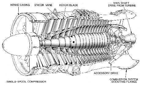
The combination of a stators row followed by a rotors row is called a stage, and each stage of industrial axial flow compressors could raise the pressure by something between 5% and 25%. This means that in order to have high pressure ratios, you need multiple stages for your compressor.
Industrial axial flow compressors are the ones you might purchase, but just to get an idea of what is out there, let us say that since these compressors are placed on the ground or ships, the flow speed is not that high; the flow is subsonic. However, aircrafts also make use of these compressors in their jet engines, and since they fly at much higher speed near the speed of sound where the flow becomes transonic, each stage of the compressor raises the pressure between 15% and 60%. There are also some laboratory designs that are still being studied that could handle supersonic air compression, pressure rise which is reported to be 80% to 120% per stage.
Axial Compressors Diagram
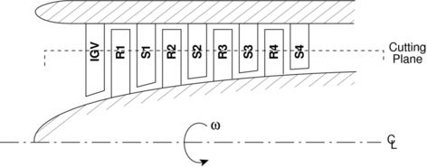
As already mentioned, the air intake of axial air compressors starts with a row of stationary blades called the inlet guide vanes. They provide a proper air direction reaching at the first stage of the compressor. The compressor stages are placed successively until the final desired pressure is achieved after the last stage of the axial compressor.
What matters here is that the space between each row of rotors and their followed row of stators in a stage should be as small as possible to ensure smoothness of air flow. Each stage is also placed as closely as possible to the next stage to provide a smooth air flow. There is also very little clearance between the stator tips and the shaft as well as between the rotor tips and casing.
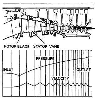
Now, as can be seen in the figure above, the space for the air as it passes through the stages of the compressor is gradually decreased. The reason behind this is for the axial velocity of the air through these compressors to remain constant as the pressure increase per stage. Another important point here is about the arrangement of the stators and rotors which is done in a way to provide diverging areas. Diverging passageways result in lowering of the speed and increase of the pressure (for subsonic flow).
The Design of Axial Compressors
Axial flow compressors are designed in a way to be able to handle some level of off-design operations. This means that they can handle when air flow and speed, or pressure ratios differ from the design point to some level. However, when the amount of deviation exceeds that limit, it could result in compressor stall and then surge for higher-than-design-point flow rates and choking of the compressor for low air flows.
The level of handling off-design operation depends on the number of stages and the overall pressure increase delivered by the compressor. By considering some design flexibility for the axial compressor such as adjustable stators, bleed valves, or multi-spool (driving shaft in driving shaft) design could help with better handling of off-design operation for axial flow compressors.
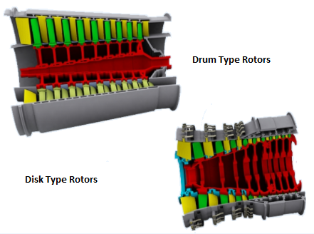
There are two configurations for compressor rotors. The first kind of rotor blade configurations for axial flow air compressors is called the drum type in which the rotors are placed on a constant-diameter driving shaft with the casing approaching the shaft as the flow goes into later stages of the axial compressor. The second type of axial air compressors are called disk type compressors in which the casing has a constant diameter, but the shaft has an increasing diameter to lower the air volume as it reaches to the outlet of the air compressor.
The drum type rotor configuration is used for industrial applications. The disk type configuration of rotors yields a light-weight design, making them the best choice for aircraft engine compressors. Nonetheless, for both of the rotor configurations, the axial component of the air velocity is kept at a more or less constant value using such gradually contracting the space between the shaft and casing. This is an important design consideration because steady air delivery after the compressor job has been done is important for the later sections of the system.
In order to deliver what these design configurations are intended for, specific materials need to be used for manufacturing of the major components of the axial flow compressors. For instance, rotors and stators are made from aluminum, titanium, nickel alloys, steel, or some fibrous composites. The casing is made from a composition of aluminum, magnesium, titanium, steel, or iron.
Some Terminology
Other than pressure ratio, or what an IGV is or what rotors or stators are, there are some other terms commonly heard when it comes to axial flow compressors. As you have probably noticed so far, the blade design and configuration is the real challenge when designing an axial compressor. And you might remember that each blade is like an airfoil; therefore, the same terminology applies here:
- Leading edge: the tip of the compressor blade.
- Trailing edge: the rear end of the compressor blade.
- Suction face: the bottom surface of each compressor blade which sees the counter direction of the shaft rotation.
- Pressure face: the upper surface of each compressor blade which sees ahead of the direction of the driving shaft rotation.
- Camber line: the line connecting all the middle points between the suction and pressure face. Well, the more accurate way of defining a camber line is the line that connects the center of all circles circumscribed by the suction and pressure surfaces.
- Chord line: the straight line connecting the leading edge and trailing edge of the blade.
- Blade angle of attack: the angle that the chord line makes with the horizon.
Applications of Axial Flow Compressors
Axial compressors are mostly used for power generation purposes. Power generation could be at power stations or large industrial plants where gas turbines are used to generate electric power. This application of axial compressors could also be found in large marine gas turbine power plants. The more challenging design and manufacturing of air compressors is for aerial gas turbines that are used for aircraft.
Apart from power generation purposes, axial flow air compressors could also be used in chemical plants such as nitric acid plants, air separation plants, and also blast furnaces that produce industrial metals such as pig iron, or even lead and copper.
Sources of Loss in Axial Flow Compressors
The purpose of a compressor is to increase the pressure of the fluid passing through it; therefore, the compressor means the loss of pressure inside the compressor. Compressor pressure losses happen in each of the stages and are due to the following reasons:
- Skin friction of the annulus walls,
- Profiles losses on blade surfaces,
- Secondary flow losses. (for further information about turbomachinery losses see here)
Axial Flow Compressors vs. Centrifugal Compressors
Dynamic compressors include the axial and centrifugal types, and their comparison is a common thing to do when you are wondering which might be the best fit to your application. Let us compare these two types from various perspectives:
| Axial Flow Compressors | Centrifugal Compressors | |
| Flow direction | Parallel to the axis of shaft rotation | Radially receding from the driving shaft (In a way perpendicular to the axis of shaft rotation) |
| Operation | Narrow off-design operation limits between choking and surging situations → Poor partial load performance | Extended off-design operation limits between choking and surging situations → Better partial load performance |
| Per-stage pressure ratio | 1.25:1 for subsonic flow operation (tops) → Multiple stages required | 4.5:1 for subsonic operation (tops) → lower number of stages required for the same overall pressure ratio as the axial compressor |
| Isentropic efficiency | 86% – 88% | 80% – 82% |
| Starting power | High | Low |
| Design and manufacturing |
|
|
| Mass flow rates | High mass flow rates | Lower mass flow rates |
| Frontal area | Smaller frontal area | Larger frontal area compared to axial flow compressors for the same mass flow rate |
| deposit accumulation sensitivity | Sensitive to deposit accumulation of the passage surfaces → lowering of performance | Almost insensitive to deposit accumulation on the passage surfaces → no performance loss |
Buy Equipment or Ask for a Service
By using Linquip RFQ Service, you can expect to receive quotations from various suppliers across multiple industries and regions.
Click Here to Request a Quotation From Suppliers and Service Providers
Read More on Linquip



It is very interesting.
Thanks for visiting our website and leaving your comment! You are encouraged to visit Linquip Tech News, where you can find similar posts.
We appreciate you taking the time to check out our page, Seth! Asking one of our specialists will help you get your problem fixed.