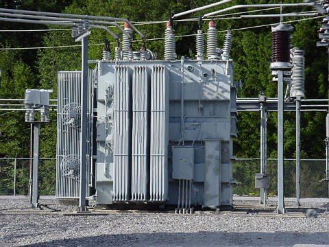
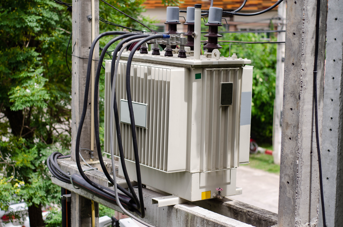
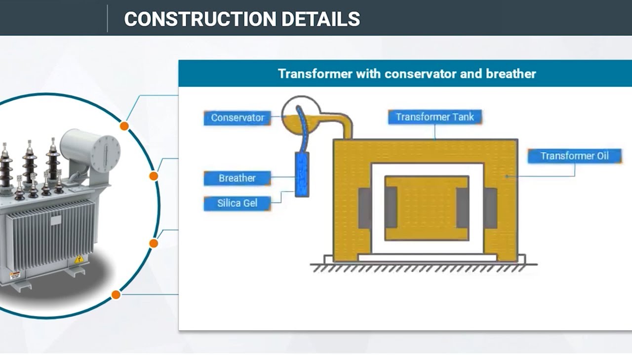
The construction of transformer and its main parts describes the way how this system converts or let’s say transfers electrical power from one circuit to another circuit. We will define the system, then present the main parts plus the construction of the transformer here at Linquip.
Interested in learning about the Functions of a Transformer? A Transformer’s functioning principle and uses may be found here at Linquip. In search of a place to purchase Transformer Equipment? Visit Linquip’s Transformer For Sale, where you can see a complete list of all Transformer Products depending on your needs and application.
For your convenience, Linquip also provides a list of Transformer Suppliers and Companies from which you may select the best one. Linquip has a wide variety of Transformer Manufacturers who can help you discover the right equipment for your application. The best Transformer Service Provider businesses can also manage your industrial equipment services activities, such as the installation, maintenance, and repair of your industrial equipment.
⇒ View a List of Gearbox for Sale and Their Suppliers ⇐
What is a Transformer?
A transformer is an electrical device composed of two or more wire coils used in a shifting magnetic field to transfer electrical energy. In other words, it is an electrical system for transforming a low voltage alternating current into a high voltage alternating current or vice versa. Usually, the energy conversion takes place with a voltage and current transition. The AC voltage is either increased or decreased by transformers.
It acts on the “reciprocal induction principle”, i.e. an induced EMF is set up in the other coil as a changing current is transmitted into one of the two inductively coupled coils.
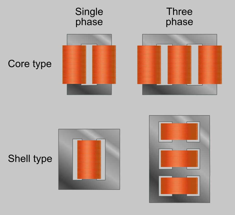
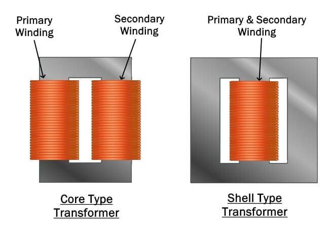
The name given to a transformer’s structure is determined by how the primary and secondary windings are twisted around the central laminated steel core. The Closed-core Transformer and the Shell-core Transformer are the two most frequent and fundamental transformer designs. The construction of a Transformer Product is made possible by the usage of Industrial Tools. Transformers are accessible from a wide range of Suppliers and Companies, as well as manufacturers and distributors, and Linquip has a large selection of Transformers for Sale.
Linquip’s website has a comprehensive list of transformer services for all OEM fleets. Suppliers of Linquip can help you with this. To learn more about how to connect with a varied collection of service providers who consistently produce high-quality products, please contact Transformer Experts in Linquip.
Construction of transformer parts
A transformer consists of several individual components that act to boost the overall functionality of a transformer. Let’s study each part of the construction of transformer one by one.
How A Transformer Is Built?
The center iron core of most transformers is formed of a highly permeable material, usually thin silicon steel laminations. These thin laminations are put together to give the appropriate magnetic route with the least number of magnetic losses possible.
What is the Construction of Transformer?
The construction of transformer is of iron core laminated with steel bands. Core laminations are constructed from insulated metal thin metal strips. These laminations are separated and wound around the limb using a sheet of coat or parchment. The winding consists of two types, main and secondary winding. These windings are isolated from each other and are made by an electric coil. The principal feature of the core is to facilitate the winding of the magnetic flow and to provide a low reticence direction with a useful flow.
The construction of transformer parts is as follows:
- Magnetic circuit
- Electric circuit
- Core Type Construction
- Shell Type Construction
- Dielectric Circuit
- Conservator
- Breather
- Explosion Vent
- Radiator
- Bushing
- Windings
- Conservatory Tank
Magnetic circuit
A transformer’s magnetic circuit consists of a core and a yoke. The direction of the magnetic flux flow is given by the circuit. A laminated steel core and the two coils form the transformer. From each other and also from the core, the two coils are shielded. The transformer’s core is made of steel sheet or silicon steel laminations assembled to provide a continuous magnetic path. The silicon steel material has minimal hysteresis losses at normal flux densities. The vertical position in which the coil is wound is called the limb, while the yoke is known as the horizontal position.
Electric circuit
The transformer electrical circuit consists of the main and secondary copper windings. Rectangular cross-section conductors are commonly used for low voltage winding as well as for high voltage winding for large transformers. Circular cross-section conductors are used for high voltage winding in a small transformer. Depending on the main structure and how the main and secondary windings are mounted around it, the transformer is referred to as the core type and shell type.
In the construction of transformer, the core of the transformer is typically built with a high permeability material, such as silicon steel laminations. Based upon the configuration of the main and secondary windings, a transformer core may be formed in two ways. Those two approaches are:
- Core Type construction
- Shell Type Construction
Core Type Construction
In the basic core style construction of the transformer, a rectangular lamination of the frame is formed to shape the core of the transformer. The laminations are cut in the form of L-shaped strips. To prevent high resistance to joints where laminations are bolted against each other, alternative layers are arranged accordingly to remove continuous joints.
The main and secondary windings are interleaved to reduce the flow of leakage. Half of the winding is wound around each limb of the core in this type and is enclosed such that there can be no magnetic flux losses and the flux leakages can be reduced. This form of the structure appears to be very helpful for the propagation of the flux, in that the windings cover each limb and thus the flux circulates through the entire heart.
Shell Type Construction
The next part in the construction of transformer is the individual laminations of a shell-type transformer that are cut into the shape of a long E and I strip. It has two magnetic circuits, and its heart has three limbs. The central limb carries the whole flow, while the side limbs carry half of the flow. The diameter of the middle is also twofold, to that of the outer limbs. The windings travel around the interior of the main ring in the shell style structure of the core so that the core forms a shell outside of the windings. As all the windings are wound around the same middle arm, this arrangement also eliminates flow leakages.
Dielectric Circuit
The dielectric circuit consists of insulations that are used to insulate leading components in various positions on the transformer. The center is laminated to reduce eddy current loss. The laminations are insulated from each other by a light covering of varnish or an oxide layer. The thickness of the laminations ranges from 0.35 mm to 0.5 mm at a frequency of 50 Hz.
That’s not the end! Withing the construction of transformer you can also find a winding and core assembly container, called “a tank”, bushings to take the terminals, an oil conservator to supply oil for cooling purposes in the transformer tank, etc.
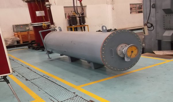
Conservator
A cylindrical tank on the top or roof of the transformer’s main tank is used for the preservative. A wide cover is provided that can be opened from time to time for proper servicing and cleaning of the transformer. It serves as a buffer for the insulating oil transformer. When the transformer is fully charged and the temperature of the transformer is high, there is a rise in the amount of air inside the transformer. If the oil level rises and falls at the same time, the conservatory provides sufficient room for this increased oil inside the transformer.
Breather
A wind functions like a heart in the construction of transformer. As the temperature of the transformer increases, the insulating oil in the transformer heats up. When the oil heats up and spreads, the transformer breathes air in and the oil is cooled down and the oil level is consumed. The oil level in the chamber rises and reduces as the breather brings the air in and out to cool the oil. This air carries moisture, which contaminates the oil and thus deteriorates the consistency of the oil. The breather is packed with Silica Gel to remove this moisture content. The key purpose of the silica gel is to isolate the moisture from the oil while preserving the consistency of the insulating oil. The color of the silica gel becomes pink as it absorbs moisture from the oil.
Explosion Vent
It is important for the construction of transformer to be safe and avoid damage; hence, there is an explosion vent, a thin aluminum pipe that is mounted at both ends of the transformer. As the temperature rises rapidly in the transformer and the excess pressure is produced, the explosive vent helps to relieve the pressure.
Radiator
Cooling the oil in the transformer is the key feature of the radiator. The radiator is a detachable tube, the upper and lower portions of which are attached to the transformer tank by a valve. When the washing and repair of the transformer are completed, the valve keeps the oil from draining when the radiator is removed from the transformer. The transformer oil is hot and moves up in the main tank while the transformer is in operating order and reaches the radiator through the upper valve. It gets cooled there, and the oil reaches the transformer tank again from the lower valve of the radiating unit and this mechanism continues.
Bushings
Bushings are the insulating system in the construction of transformer that enables an electrical conductor to safely transfer electrical energy through it. When a significant volume of electrical energy travels through it, it provides electrical field power to withstand the insulation of the conductors. In smaller transformers, solid porcelain type bushing is used, and in large transformers, oil-filled condenser type bushing is used. The most common cause of bushing failure resulting in damage to the transformer is the moisture inlet. The power factor of the bushing will still be in a stable state, so if the power factor difference is seen, the insulation will deteriorate. The measures known as acceptance or routine tests and Doble Power Factor Tests will define this.
Windings
Winding arrangements are also an important concern in the construction of transformer. A transformer’s windings are made up of a conducting material to allow the magnetic flow to build up and the current can then be transferred from one winding to another. To raise the magnetic flux, these windings are wound on two different iron limbs, as iron is an important conductor and exhibits excellent magnetic properties.
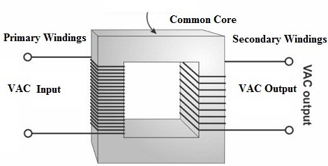
They are often insulated from each other by these coils. Since both of these coils are wound on two different limbs, flow leakages often occur due to the distance between them, decreasing the magnetic flow density and resulting in a decreased magnetic coupling between the two coil windings.
Conservatory tank
Since it is often important for a kind of container to hold the transformer core and windings in to tightly insulate them, a tank is used to preserve the laminating fluid, reduce its oxidation and maintain oil levels. This tank also involves several other critical arrangements, such as a set of substantial sensors and a relay sensing gas, which serves as a gas sensor and rings a warning if the presence of some undesirable gas is sensed and the external circuitry is automatically protected by disconnecting the transformer.
What Is A Transformer Symbol?
A transformer’s schematic symbol may appear to be two coils (called windings) positioned next to each other, but the magnetic coupling and orientation between these two coils are also depicted.
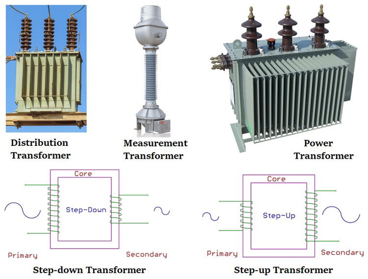
What Are 2 Types Of Transformers?
The capacitor voltage (potential) transformer and the conventional wound type (or electromagnetic) transformer are the two types of potential transformers.
ِDownload Construction of Transformer PDF
For a better understanding of the basics of Transformers, their working principle, and types look at this PDF that can help you better understand Transformers.
Conclusion
That’s all about the construction of transformer. In the post, we threw some light on the definition of a transformer, its parts, and how it is constructed. If you are interested in gaining more information about the construction of transformer, register at Linquip and let us know that in the comments section. Please share this post with other friends.
Buy Equipment or Ask for a Service
By using Linquip RFQ Service, you can expect to receive quotations from various suppliers across multiple industries and regions.
Click Here to Request a Quotation From Suppliers and Service Providers
Read More on Linquip
- Types of Transformer: An Article About How Transformers Differ in Construction and Design
- Difference Between Step-Up and Step-Down Transformer: A Quick Guide
- working principle of transformer: discover the mechanism involved in the operation
- What is the Efficiency of Transformer?
- What is Step Up Transformer?
- What is Step-Down Transformer and Its Application?
- What is Electrical Transformer?
- What is Auto Transformer? Advantages & Application
- Current Transformer Types and Applications
- Construction of Transformer: Uncover The Parts and Construction
- What is the Equivalent Circuit of Transformer?
- Difference Between Step-Up and Step-Down Transformer: A Quick Guide
- Types of Transformer: An Article About How Transformers Differ in Construction and Design
- What is the Current Transformer?
- Top Transformers Manufacturers and Suppliers in the USA and Worldwide

