A Step-up or Step-down Transformer is a static device with no moving components, which transmits electrical power from one circuit to another. Voltage and current changes during this process, while we have no change in frequency.
Power streams that are received at the local distribution level have their voltage reduced by Step-Down Transformers. Each consumer node steps down the long-distance stream once to a level suitable for local distribution and once more (residential homes and offices). Several Suppliers and Companies, as well as other manufacturers and distributors, supply step-down transformers, and there are numerous Step-Down Transformers for Sale on Linquip.
A Step-up Transformer is a machine that converts the low primary voltage to a high secondary voltage and steps up the input voltage. On the other hand, a step-down transformer steps down the input voltage. We have a lower secondary voltage compared to the primary voltage.
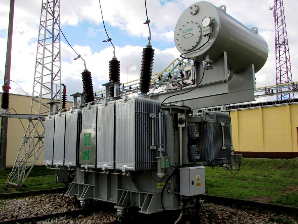
The following images show a simple illustration of transformers’ use (step-up and step-down transformers) in a regular transmission system.

What are the Differences Between Step Down and Step Up Transformers?
Transformers are categorized into several types depending on the construction, voltage ratings, type of cooling, the place where it is employed, number of phases of the AC system, etc. Here we will discuss step-up and step-down transformers, which are classified based on the conversion of voltage level.
Step-up Transformer
In a step-up transformer, we have a larger secondary voltage compared to the original voltage. It is expected because of the lesser number of coils on the first side rather than the secondary. A Step-up transformer is employed to boost the voltage to a higher level. These are installed in transmission systems and are considered at higher power levels.
Step-down Transformer
In a step-down transformer, we have a lesser secondary voltage than the original voltage because of the fewer turns in the secondary winding. Therefore, this type of transformer is used to decrease the voltage to designed levels for the circuit. Almost most of the power supplies have the step-down transformer to hold the circuit running range to defined safer voltage limits. These transformers are usually installed in electronic circuits (electronic transformers) and distribution systems (power transformers).
It should be noted that a transformer is a reversible machine so that it can be employed as both a step-up and step-down transformer. For instance, if the circuit requires a high voltage, we would connect the HV terminals to the system, whereas the circuit or load needs a low voltage, we would connect the LV terminals to the system.

The turn ratio determines the ratio of the voltage in a transformer. By using a larger number of turns in the winding, we will have a higher produced voltage in it. A step-down transformer has a lesser amount of turns on secondary to make a low voltage and more turns on primary to resist high voltage levels of the AC supply.
The turns ratio = N_P /N_S = V_P /V_S
Turns Ratio = Primary Turns/ Secondary turns = Primary Voltage/ Secondary Voltage
What is the Construction of Transformer?
The construction of the transformer is of an iron core covered with steel bands. Core laminations are composed of insulated thin metal strips. Laminations are separated and twisted around the limb employing a sheet of coat or parchment. The winding is consists of two sides: main and secondary winding. Both windings are made by an electric coil and isolated from each other. The core’s principal feature is to facilitate the winding of the magnetic flux and provide a useful flow in low reticence direction. For more information about the parts of transformer click here.
The parts of the transformer are as follows:
- Electric circuit
- Magnetic circuit
- Shell Type Construction
- Core Type Construction
- Dielectric Circuit
- Conservator
- Bushing
- Breather
- Explosion Vent
- Radiator
- Windings
- Conservatory Tank
What is the Working Principle of Transformers
An electrical transformer’s working principle is “Mutual Induction”, which states: a uniform current variation in a coil will produce an E.M.F in the other coil, which is inductively linked to the first coil. A transformer includes two coils with high mutual inductance, which are electrically separated but have a typical magnetic circuit in its basic form. The following figure shows the basic structure of a Transformer working as a step-down transformer.

The Primary Coil or Primary Winding coils, the first set of coils, are connected to a Primary Voltage, an alternating voltage source on the first side. The other set of coils, which is called Secondary Winding or Secondary Coil, is connected to the load. The load draws the alternating outcome voltage (stepped down or stepped up voltage).
The alternating input voltage excites the Primary Winding, and an alternating current flows in the winding. The alternating current makes an alternating magnetic flux, which passes in the magnetic iron core and completes its path.
According to Faraday’s Law, an E.M.F is produced in the secondary winding since the secondary winding is also connected to the alternating magnetic flux. The intensity of the voltage at the secondary winding is based on the number of windings flux gets passed through. Therefore, without making an electrical contact, the primary winding’s alternating voltage is transferred to the other winding.
It should be noted that depending on the type of the transformer, the voltage at the secondary side of the transformer may be the same, lower or higher compared to the primary of the transformer. However, but the period of the voltage and its frequency do not change.
What is Step Down Transformer?
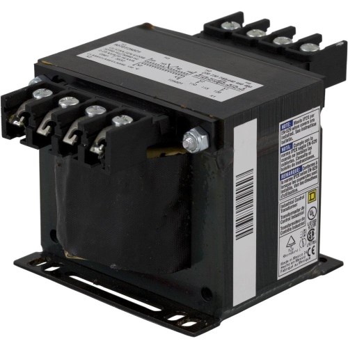
A Step-down Transformer is a transformer that converts a high voltage at the primary windings to a low voltage at the secondary windings. In terms of the coil windings, a step-down transformer’s primary winding has more turns than the secondary winding. The following image shows a typical step-down transformer.

Power in Step-down Transformer
We can measure the power of a transformer by using the voltage and current in the system. The power amount in a transformer is determined in VA, Volt-Amps (for larger transformers Kilo Volt-Amps, kVA).
Ideally, the power on both sides of any transformer is constant, which means the available power at the transformer’s secondary side is the same as the power at the transformer’s primary side. This is relevant to a step-down transformer too. However, as the voltage at the secondary side of a step-down transformer is lower than that at the primary, the current would be increased at the secondary to balance the absolute power in the transformer.
Voltage and Current Relation in Step-Down Transformer
Consider VP as the voltage, and IP as the current, and PP as the power at the transformer’s primary side. As we know, the power can be computed by just multiplying the current and voltage. Therefore, the power is given at the primary side of the transformer by
P_P = V_P \times I_P
Similarly, considering VS as the voltage, IS as the current, and PS as the power at the transformer’s secondary side. The power is given at the secondary of the transformer by
P_S = V_S \times I_S
Because of the equality of the power in a transformer, we have:
P_P=P_S
V_P\times I_P = V_S\times I_S
As VS is lower than VP in a step-down transformer, IS has to be larger than IP. So, the output voltage in a step-down transformer is smaller than that of the primary voltage, while the output current is higher than the input current.
Based on the above equations, we can determine a step-down transformer as a machine that converts a high voltage and low current alternating input to a low voltage and high current alternating output.
As mentioned before, the power calculation presented above is for an ideal transformer with no loss. There will be losses in the form of copper loss and iron loss that should be considered even if these losses are small.
Wiring a Step-Down Transformer
We can wire a Step-Down Transformer as the presented instruction:
- We should identify the rating and schematic of the step-down transformer before installing it. First, we remove the terminal connection box cover.
- Know termination description and follow all step-down transformers: H1, H2, H3, and H4 signify the transformer’s high voltage side or power feed end. The interconnection of a transformer may vary based on the voltage used for feeding the transformer and the manufacturer.
- Cut feed power wires to length. In the case of using large wire lugs, we should consider the lug’s size and the length of the wire that we can insert into the female crimp area.
- Strip back the exterior insulating of the wires with the wire strippers or knife. Insert the wire lug or eye-ring over the stripped copper wire and crimp the junction device permanently to the wire, using the proper-size crimper.
- Terminate the high voltage of the step-down transformer. In the case of bolts at the high side terminals, try to follow any manufacturer lists’ torque requirements.
- Terminate the low voltage of the transformer. These terminals will be recognized by X1, X2, X3, and X4. Again read the manufacturer’s individual schematics for that specific type of transformer you use. On the small control transformers, there would be only an X1 and X2. Power is X1 or “hot” side, and X2 is commonly the grounding and neutral part of the low voltage.
- Open the small control transformer. X1 will go right to the control circuit after crossing through a small fuse rated for the circuit. X2 will be connected to the neutral side of the control circuit and the grounding safety. It means that we should tie the X2 side of the small control transformer to the electrical circuit’s grounding.
- Close any enclosures and all covers on the transformer to protect you from electricity. Connect the high voltage to the transformer by turning on the feeder power supply. Switch on the low side safety control.
- Utilize a voltmeter for testing proper voltage on the second side of the step-down transformer. It should be equal to the values listed on the specs tag presented by the manufacturer.
Checking a Step-Down Transformer
By the following instruction, we can check if the transformer is running properly or why it stopped working:
- Use a screwdriver to remove all wires from the transformer terminals. Distinguish the cables if they are not already recognized. Mark each terminal and the wire connected to it.
- Use an ohmmeter. Connect one head to the metal frame and the other to the transformer’s terminals in the subsequent sequence: H1, H2, X1, and then X2. The ohmmeter should show wide open or infinite ohms. In some cases, the ohmmeter shows any form of resistance, so there is an internal problem related to the windings. Coils are shorted to the frame of the transformer, and it will have to be replaced.
- You should check the continuity of each coil with an ohmmeter. Connect one end to H1 and the other to H2. Usually, it should state resistance in the range of 3 to 100 ohms, based on the transformer style and type. Do the same for the X1 and X2 terminals and check if they have the same results. In the case of reading wide-open or infinite ohms, the wires are divided.
- Conduct the transformers isolation circuit with an ohmmeter. Connect the one end to H1 and the other to X1. The meter should express a wide-open circuit or infinite ohms. Do the same for H2 and X2, respectively. By observing any resistance, the isolation of the transformer must be replaced as it has been compromised.

Step Down Voltage Transformers Specifications
For converting low-current, high-voltage power into low-voltage, different step-down voltage transformers are constructed in the following specifications.
Voltage: Low output voltage and high input voltage
Winding: Primary winding are high-voltage winding
Current: Secondary winding has a high current
Output Voltage’s Rate: 10v, 20v, 24v, 110v, etc.
In addition to the mentioned features, the step-up and step-down transformers are available in the presented specifications:
- Flying leads
- Voltage IN: Voltage OUT definition
- Single or multiple outputs
- Isolation
- PC Mount
- X:Y ratio definition
Applications of Step-Down Transformers
Transformers are utilized to increase the voltage for transmission and decrease the voltage for utilization in the military, medical, telecommunication, electronics industries, etc. Some examples for their application are:
- Providing 1:1 Isolation
- Power Plants (220V to 110V conversion and 110V to 220V conversion)
- Substations
- Electrical and electronic equipment
- Doorbells
- Tv sets
- Refrigerators
- Musical/entertainment
- Rectifier circuits
- Inverters
- Medical equipment
- PCB circuit modules
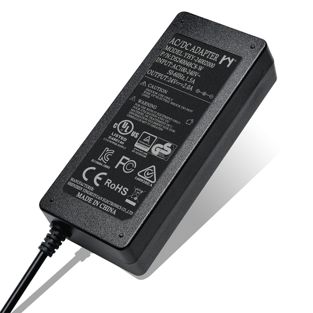
These were the application of transformers, but we should remember that almost all low voltage wall adapters use step-down transformers for wide usage of switching power supplies. Also, All the street transformers near our cities and homes are step-down transformers. They have an 11kV alternating input voltage and convert it to 230V for sharing to our homes. Step-down transformers are generally used to transform the 220-volt electricity to the 110 volts required by north American devices.

Step Down Transformer’s Real-Time Application
The voltage in the power plants or generation stations is approximately 20kV. It is stepped up to 440kV by using a step-up transformer to send this voltage over long distances to our home. This voltage is transmitted to a distribution station, and a step-down transformer reduces it to 11kV.
Can We Use Step-Down Transformer and Step Up One Alternately?
It is feasible to operate both of these transformer types backward, using an AC source to power the secondary winding and connecting the primary winding to a load. So by performing the opposite function, a step-down can function as a step-up and visa-versa. One of the conventions employed in the electric power industry is the usage of “H” designations for the winding (with higher voltage like the primary winding in a step-down system and the secondary winding in a step-up one) and “X” designations for the winding with lower voltage.
One of the most critical considerations to enhance transformer efficiency and decrease heat is picking the windings’ metal type. Copper windings are significantly more efficient than aluminum and various winding metal choices; however, it also costs more. Transformer with copper windings is expensive to purchase at the beginning. Still, it saves on electrical costs in the future.
Buy Equipment or Ask for a Service
By using Linquip RFQ Service, you can expect to receive quotations from various suppliers across multiple industries and regions.
Click Here to Request a Quotation From Suppliers and Service Providers
Read More on Linquip
- What is Step Up Transformer?
- Difference Between Step-Up and Step-Down Transformer: A Quick Guide
- Types of Transformer: An Article About How Transformers Differ in Construction and Design
- What Is Auto Transformer
- What Is Electrical Transformer
- Top Transformers Manufacturers and Suppliers in the USA and Worldwide
- Working Principle of Transformer: Discover the Mechanism Involved in the Operation
- Difference between Power Transformer and Distribution Transformer
- What is the Efficiency of Transformer?
- Difference Between Step Up and Step Down Transformer
- What is a Distribution Transformer?
- What is a Single Phase Transformer?
- What is Power Transformer?
- Current Transformer Types and Applications
- What is the Current Transformer?
- What is Potential Transformer?


Would like to know more about converting low voltage/current to the one using on our home.
For example electric energy from a windmill to a residential home.
Dear Bulkan
Thanks for your Attention
We already have an article about your comment.