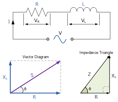
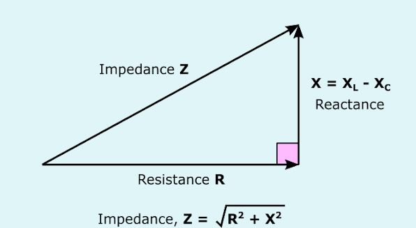
There is a comprehensive guide to impedance and reactance in this post. It is possible to describe an element in a DC circuit by its resistance alone. In a DC circuit, a capacitor’s resistance corresponds to an open circuit (infinite resistance), whereas the resistance of an inductor comes in the form of a short circuit (zero resistance). As a result, capacitors and inductors would be wasted in an ideal DC circuit. Despite this, they are still used in real circuits since the voltages and currents are never ideally constant.
Linquip provides you with a comprehensive overview of inductors, resistors, and capacitors. More information on Linquip’s electrical solutions can be found on our “Electrical” page. You can simplify your task by learning about resistors and capacitors now.
It may be difficult for you to select the right circuit components. With Linquip, you can find the Electrical Products that meet your needs. Linquip’s platform allows you to receive free quotes from a number of Electrical Suppliers and Companies.
Due to the current flowing in one direction, DC circuits are relatively simple to analyze, with resistance being the primary component. On the other hand, AC circuits have more complexity because voltage and current alternate directions at a given frequency. AC circuits also have a property called reactance, which is different from DC circuits, which have resistance. Resistance and reactance make up impedance. We will review some basics and terms in this post.
Resistance
It is essentially friction that prevents current from flowing. Conductors (except superconductors!) contain it to some extent, most notably resistors. When an alternating current passes through a resistance, there is a voltage reduction that is in phase with the current. Symbolically, resistance is represented by the letter “R” and measured in ohms (Ω).
Reactance
Reactance is basically inertia against current flow. The presence of this phenomenon can be found everywhere electric or magnetic fields develop in response to voltages or currents applied, but capacitors and inductors are particularly notable examples.
When the alternating current passes through a pure reactance, there is a voltage drop with a 90° phase difference with the current. Reactance can be expressed mathematically as the letter “X” and is measured in ohms (Ω).
Impedance
The term encompasses resistance and reactance that oppose current flow. All circuits and components contain it.

When an alternating current passes through an impedance, there is an out-of-phase voltage drop between 0° and 90°. An impedance is mathematically represented by the letter “Z” and measured in ohms (Ω), in complex form.
A perfect resistor has resistance, but not reactance. There is no resistance in a perfect inductor or capacitor, but there is reactance in them. Since all components have impedance, it is logical to convert the values of each component (resistance, inductance, capacitance) into impedance terms before analyzing an AC circuit.
A component’s impedance phase angle can be defined as the phase shift between the voltage across it and the current through it.
Voltage drop and current are both in phase for a perfect resistor, so the impedance angle is 0° for a resistor. Inductor impedance phase angles are +90°, since for perfect inductors, voltage drop necessarily leads current by 90°.
In the case of a perfect capacitor, the voltage drop always lags the current by 90°, making the capacitor’s impedance phase angle -90°.
The impedance of a system is a complex number composed of a real and an imaginary part:
Z=R+jX
Z represents the complex impedance. X represents reactance, while R represents resistance. Resistance has always positive value, but reactance can also be negative. Power is dissipated by resistance in a circuit as heat, whereas energy is stored by reactance as electric or magnetic fields.
AC impedances behave similarly to DC resistances: i.e., they add in series and decrease in parallel. This is how Ohm’s Law would look if it was based on impedance instead of resistance:
U=IR (Ohm's law for DC circuits)
\underline{U}=\underline{I}.\underline{Z}
U represents the complex voltage between two points, I denotes the complex current, and Z indicates the complex impedance.
Initially, complex voltages and currents can seem a bit overwhelming, so let’s go over them. An AC circuit is typically in a steady state when one or more power sources create a sinusoidal output at the same frequency. In this case, it can be shown that all the voltages and currents oscillate at the same angular frequency, ω. There is, however, a phase difference between these voltages and currents. Using the example below, a cosine wave can be used to represent the voltage in an AC circuit:
u_t=U_M.{\mathrm{cos} \left(\omega t+{\phi }_U\right)\ }
where u(t) refers to the voltage between two points in a circuit as a function of time, UM represents amplitude, ω corresponds to the angular frequency, and ΦU indicates phase. As a result, this voltage has a complex representation:
\underline{U}=U_M.e^{j{\phi }_U}=U_M({\mathrm{cos} \left({\phi }_U\right)+j.{\mathrm{sin} \left({\phi }_U\right)\ })\ }\
Typically, one signal is used as a phase-reference signal on a circuit-wide scale. Therefore, all other signals (voltages and currents) are phased based on the assumption that the phase of that signal is zero.
Connection in Series
Simple addition results in the equivalent impedance of two series impedances:
Z_e=Z_1+Z_2
Addition of two complexes can be performed easily by following these steps:
Z_1=R_1+{jX}_1
Z_2=R_2+jX_2
Z_e=\frac{R_1+R_2}{j\left(X_1+X_2\right)}
Using the following formula, one can calculate the effective impedance, or magnitude of the impedance:
{\left|Z_e\right|}^2=R^2+X^2
Connection in Parallel
It is first necessary to define admittance in order to determine the equivalent impedance of two impedances that are paralleled. A siemens (1 S) is the unit of admittance, and it is used to indicate how easily current flows through an element, and its value is the inverse of its impedance:
Y=\frac{1}{Z}
When two impedances are connected in parallel, their equivalent admittance is equal to the sum of their individual admittances:
Y_e=Y_1+Y_2
Z_e=\frac{1}{Y_e}
Impedance of a Resistor
The behavior of resistors in AC circuits is the same as that of those in DC circuits. In general, a resistor’s impedance consists of only the real part, which equals its resistance. Therefore, a resistor’s impedance can be written as follows:
Z_R=R
Z represents the impedance, and R represents the resistance. Clearly, a resistor has no reactance, so it cannot store energy. The current flowing through a resistor will also be in phase with the voltage when a voltage is applied across it.

Impedance of a Capacitor
Components called capacitors introduce a certain amount of capacitance into a circuit. Electrical energy is temporarily stored in the form of an electric field. Despite being technically correct, this definition isn’t very useful to hobbyists or engineers. A capacitor may be better described as a device that lags the voltage by 90 degrees in relation to the current, in the time domain. In other words, voltage lags behind current in a capacitor, and thus, capacitor current is 90 degrees ahead of capacitor voltage. The following equation is used to represent the capacitor impedance using complex numbers:
Z_C=-j\frac{1}{\omega C}
where ZC represents the capacitor’s impedance, ω indicates angular frequency, and C describes the capacitor’s capacitance.
Angular velocity is given by the following equation, where f refers to the frequency of the signal.
\omega =2\pi f
The formula of the impedance of a capacitor reveals a number of facts:
- An ideal capacitor has infinite resistance.
- For all frequencies and capacitance values, an ideal capacitor’s reactance and impedance are negative.
- The effective impedance of a capacitor varies with the frequency, and in ideal capacitors, it always decreases as the frequency increases.

Impedance of an Inductor
An inductor is also a component that introduces a certain amount of inductance into a circuit. They store electrical energy as magnetic fields. Consequently, inductors are used to delay the current by 90 degrees in comparison to the voltage.
A capacitor’s current is 90 degrees behind the voltage of an inductor. An inductor’s impedance can be calculated using the following equation:
Z_L=j\omega L
In this equation, ZL denotes the impedance of the inductor, ω represents the angular frequency, and L corresponds to the inductance of the inductor. From this formula, we can draw several conclusions:
- An ideal inductor has no resistance.
- Regardless of frequency and inductance, the reactance and impedance of an ideal inductor are positive.
- The absolute value of the effective impedance of an inductor depends on the frequency and increases with the frequency of ideal inductors.
Conclusion
In this article, we reviewed two of the most important terms in electrical circuits: reactance and impedance. In addition, we briefly discussed the equations governing the behavior of some important circuit components using these concepts: resistor, capacitor, and inductor. Whether you are looking for circuit components for a specific application or would like advice about choosing the right one, Linquip Electrical Experts are available to assist you. You can also access a variety of Linquip Electrical Experts through Linquip if you need any services regarding your equipment or electrical devices.
Download PDF for Guide to Impedance and Reactance
You can download the PDF format of this post from the link provided here.
Buy Equipment or Ask for a Service
By using Linquip RFQ Service, you can expect to receive quotations from various suppliers across multiple industries and regions.
Click Here to Request a Quotation From Suppliers and Service Providers
Read More on Linquip
- Difference Between Resistance and Impedance- Resistance vs. Impedance
- What is Capacitor and How it Works?
- Types of Resistor: Classification, Application, and Finally Clarification
- What is Parallel Circuit? Definition & Example
- What is Series Circuit? Definition & Example
- Thermistor Resistance: How does it Calculate?
- What is Resistive Circuit? Example & Diagram
- What is Capacitive Circuit? Formula & Function
- Parallel Circuit Current Calculator: A Comprehensive Guide on Linquip Platform
- Unveil the Power of Linquip’s Series Parallel Circuit Calculator


