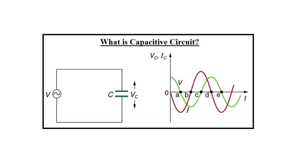
What is a Capacitive Circuit, and how does it work? A Pure Capacitor Circuit is a circuit that contains a pure capacitor with capacitance C farads. The capacitance of capacitors is the effect of storing electrical power in the electric field. It’s also known as the condenser. The dielectric material separates two conductive plates, which make up the capacitor. Glass, mica, paper, oxide layers, and other materials make up the dielectric substance. The current leads the voltage by 90 degrees in a pure AC capacitor circuit.
Linquip makes all efforts to provide as much information as possible about the capacitive circuit. Linquip is the best resource for information concerning this kind of electrical equipment. If you have any questions or concerns about circuits, you can always reach out to Linquip experts. It is recommended that you begin by reading Linquip’s article titled “What Is Electrical?“. This article will help you better understand industrial electrical equipment.
You will have to sign up as a Linquip Expert in order to use all of the Linquip platform’s features to their fullest potential. It can be very convenient for you to register for a Linquip expert account that allows you to present your skills in the area of industrial equipment in a way that ensures that they match those of the industry. Would you be interested in writing a guest post for the Linquip website? With Linquip’s Guest Posting feature, you can directly publish your content on our platform.
What is a Capacitive Circuit?
When a voltage is supplied across the capacitor’s plates, an electric field is created across them, but no current flows between them. When a variable voltage source is connected across the capacitor plates, the charging and discharging of the capacitor cause current to flow through the source.
Definition of Capacitive Circuit
A capacitor is made up of two dielectric plates separated by a dielectric medium. It stores energy in the form of electricity. The capacitor acts as a storage device, charging when the power is turned on and discharging when the power is turned off. It is charged to the value of the applied voltage if it is connected to a direct supply. Visit here to see the principle of the capacitive circuit.
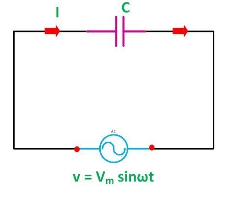
Let’s say the circuit’s alternating voltage is given by the equation:
V={V}_{m}sin(\omega t)
The charge on the capacitor at any given time is calculated by q=CV. The equation for current passing across a circuit is i=dq/dt. Thus, we can derive the value of q from the above equation by putting it into the current equation. As a result, we have:
i=\frac{{V}_{m}}{{X}_{C}}sin(\omega t+ \pi /2)
Capacitive Reactance is defined as the opposition supplied by a pure capacitor to the flow of alternating current (XC = 1/ωC).
When sin (ωt + /2) = 1, the current value will be at its highest. As a result, the maximum current Im value will be as Im=Vm/XC.
By changing the value of Im in the above equation, we get:
i={I}_{m}sin(\omega t+ \pi /2)
Phasor Diagram and Power Curve
The current flowing through the capacitor leads the voltage by 90 degrees in the pure capacitor circuit. The phasor diagram and voltage, current, and power waveforms are illustrated below:
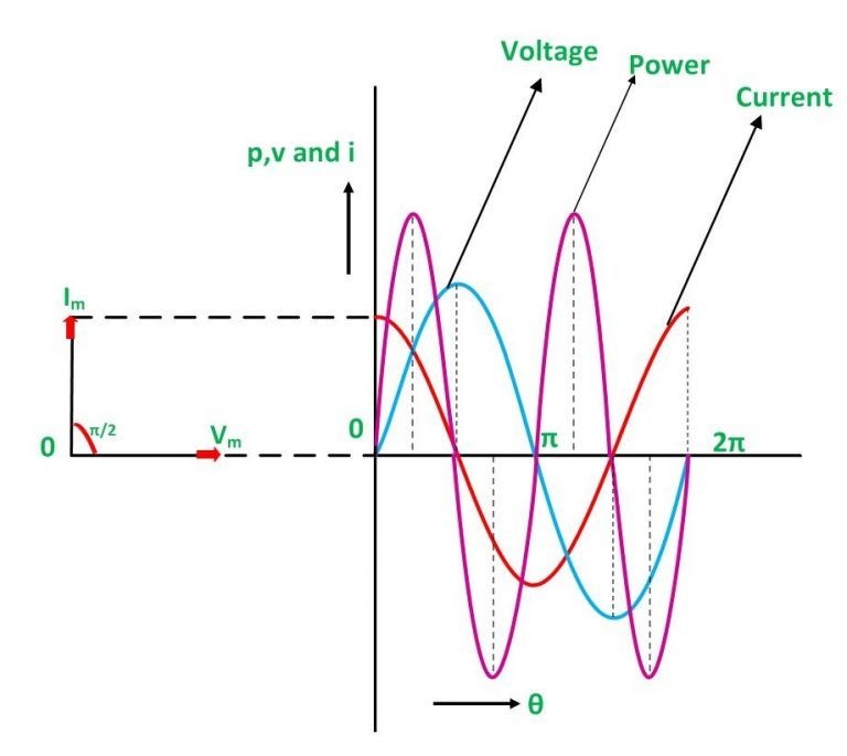
In the waveform above, the red color represents current, the blue color represents voltage, and the pink color represents a power curve.
When the voltage is raised, the capacitor charges up and reaches or exceeds its maximum value, resulting in a positive half cycle. The capacitor is discharged as the voltage level lowers, resulting in the negative half cycle.
If you look at the curve closely, you’ll note that when the voltage reaches its highest value, the current is zero, indicating that there is no current flow at that point.
When the voltage is reduced until it reaches a value, the voltage becomes negative, and the current achieves its maximum value. The capacitor begins to discharge as a result. The capacitor’s charging and discharging cycles continue.
Because of the phase difference, the voltage and current values are not maximal at the same moment. They are 90 degrees out of phase with each other. The waveform also includes a phasor diagram, which shows that the current (Im) leads the voltage (Vm) by an angle of π/2.
Power in Pure Capacitive Circuit
The capacity to have instantaneous power is provided by P = VI.
P=\frac{{V}_{m}}{\sqrt{2}}\frac{{I}_{m}}{\sqrt{2}}sin(2\omega t), or P=0
As a result of the above calculation, it is evident that the capacitive circuit’s average power is zero. Because the positive and negative loop areas in the waveform displayed are the same, the average power in a half cycle is zero.
The power supplied by the source is stored in the electric field created between the capacitor plates during the first quarter cycle. The electric field weakens in the following quarter cycle, and the power stored in the field is returned to the source. The capacitor circuit consumes no power because this procedure is performed indefinitely.
How Capacitors Behave in AC Circuits
When an alternating current is applied to a capacitor, what happens? Capacitors are different from resistors in that they allow a flow of electrons through them directly proportional to the voltage drop. While resistors allow a flow of electrons through them directly proportional to the voltage drop, capacitors oppose changes in voltage by drawing or supplying current as they charge or discharge to the new voltage level.
As long as the supply voltage is present during a direct current (DC) connection, capacitors become charged to the value of the applied voltage, acting as a temporary storage device and retaining or holding this charge indefinitely. A charging current will flow into the capacitor at a rate equal to the rate of change of electrical charge on the plates, against any changes in voltage.
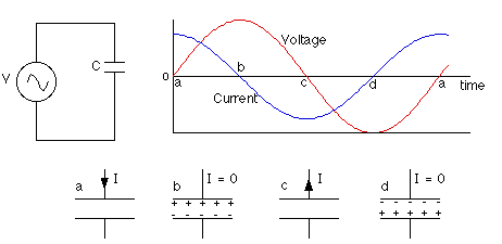
Consider the circuit in the diagram above, which consists solely of a capacitor and an AC power supply. It turns out that the current and voltage have a 90-degree phase difference, with the current reaching its peak 90 degrees (1/4 cycle) before the voltage does. An oscillating voltage is produced by the AC power supply.
The higher the current, the more charge must flow to build up a certain voltage on the plates, and the larger the capacitance. The shorter the time available to change the voltage, the greater the frequency of the voltage, and thus the larger the current must be. As the capacitance and frequency rise, the current increases.
Capacitive AC Circuits
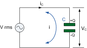
A completely capacitive AC circuit, such as the one depicted in the diagram above, consists of an AC voltage supply and a capacitor. The capacitor is connected to the AC supply voltage directly. The capacitor charges and discharges in response to changes in the supply voltage. A current will flow across the circuit, initially in one direction and later in the opposite direction.
The capacitor, on the other hand, does not carry any current. Electrons accumulate on one plate and are rapidly drained from the other, providing the impression that current is flowing through the insulator separating the plates.
Capacitive Reactance
The rate of change in voltage across a capacitor is exactly proportional to the flow of electrons across it. In AC circuits, capacitive reactance is the opposition to current flow in a fully capacitive circuit. Because reactance, like resistance, is measured in ohms, it is given the symbol X to distinguish it from simply resistive values. The capacitive reactance is calculated using the equation below, which is dependent on both the capacitor value in farads and the frequency of the AC waveform.
\frac{1}{2\pi fC}=\frac{1}{\omega C}
The formula shows that increasing either the frequency or the capacitance reduces the overall capacitive reactance. As the frequency approaches infinity, the capacitor reactance would decrease to zero, similar to a perfect conductor.
Capacitive Reactance Against Frequency
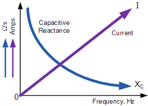
A capacitor’s capacitive reactance reduces as the frequency across its plates rises. As a result, capacitive reactance is proportional to frequency in the inverse. The electrostatic charge on the plates (its AC capacitance value) opposes current flow, while the capacitive reactance on the plates remains constant.
This means that the capacitor will have an easier time entirely absorbing the charge change on its plates during each half cycle. In addition, when the frequency rises, the current flowing into the capacitor increases in value due to the increased rate of voltage change across its plates.
The effect of extremely low and extremely high frequencies on the reactance of a pure AC Capacitance can be presented as follows:

What Is the Difference Between Capacitive and Inductive Circuits?
The equivalent impedance of the load network can be determined if both inductors and capacitors are present. Inductive loads have an imaginary part of the equivalent impedance that is positive, capacitive loads have one that is negative, and resistive loads have one that is zero.
Download What is Capacitive Circuit? PDF
Buy Equipment or Ask for a Service
By using Linquip RFQ Service, you can expect to receive quotations from various suppliers across multiple industries and regions.
Click Here to Request a Quotation From Suppliers and Service Providers
Read More In Linquip
- Types of Electric Circuits: All Classification with Application
- How does a Circuit Breaker Work?
- What is Linear Circuit
- What is RC Circuit?
- What is RLC Circuit
- Types of Resistor: Classification, Application, and Finally Clarification
- What is Parallel Circuit? Definition & Example
- What is Series Circuit? Definition & Example
- What is a Closed Circuit? Definition & Example
- What is Short Circuit? A Clear Definition & Protection Guide
- Difference Between Linear and Nonlinear Circuits
- What are the Differences Between Series and Parallel Circuits?
- The 8 Best Circuit Breaker Locators in 2022
- What is LC Circuit? Formula, Equitation & Diagram
- What is Open Circuit? Diagram & Example
- What is Inductive Circuit?
- What is AC Circuit and Its Characterization?
- Circuit Breaker vs Fuse- What are the Main Differences?
- What is the Equivalent Circuit of a Transformer?
- Potentiometer Connection, Working, Circuit Diagram, & Wiring Guide
- Difference Between Relay and Circuit Breaker: Everything You Need to Know
- Difference Between Isolator and Circuit Breaker: Ultimate Guide
- Piezoelectric Transducer and Its Impressive Applications in Electric Circuits
- What is Vacuum Circuit Breakers?
- Types of Circuit Breaker: A Basic Guide to Know Different Classifications
- A Complete Guide to Impedance and Reactance

