Resistance vs. Impedance- The main difference between Resistance and Impedance is their behavior to AC and DC currents. While resistance controls the flow of AC and DC current, Impedance just determines the alternative current flow. It means that impedance is only used in AC systems and does not have any use in DC diagrams. Another considerable difference for identifying resistance vs. impedance is that impedance can be combined with inductive reactance, resistance, or capacitance reactance. While resistance only means the resistance of an instrument. We must know their application in AC and DC circuits before understanding the resistance vs. impedance term. It should be considered that both calculation method of value is the same with R=V/I equation (Ohm’s Law).
Introduction to Difference Between Resistance and Impedance
Knowing the differences between resistance and impedance requires to consider several factors such as the fundamental explanation of them, real and imaginary numbers, the form of systems they can apply in, their symbolic representation, other elements on which they depend, the influence of frequency on them, power consumption, phase shift, and saved energy.
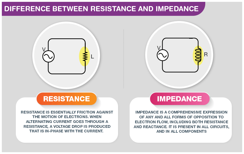
Resistance is introduced based on the movement of the electron in a conductor causing by the ionic lattice of the material which provides the conversion of electrical power in heat. It should be considered that electrical resistance is the opposite form of steady-state current. A complete resistance varies with frequency if subjected to a DC system.
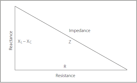
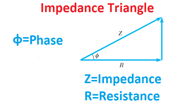
Impedance is the identification of the nature of AC electrical circuits which is formed based on capacitance and inductance. This value also modifies with the frequency. Impedance and reactance are usually presented as the same instruments and are interchangeably employed. It is essential to notice that reactance is the resistance subjected to the AC diagram by capacitors and inductors while impedance is the value that is evaluated by sum of the reactance and resistance. In the next figure, Impedance tringle is given which defines the resistance vs. impedance term schematically. Visit here to explore more about the differences between resistance and impedance.
Because we know how to provide a current or voltage as a phasor, we can provide this relationship when set to main passive circuit sections like resistance when attached to a single-phase AC source.
Any complete main circuit instrument such as a resistor can be presented mathematically based on its current and voltage, and in the instructions about resistors, we can see that the voltage within a pure ohmic resistor is directly related to the current-flow through it as explained by Ohm’s Law.
Resistance with a Sinusoidal Supply
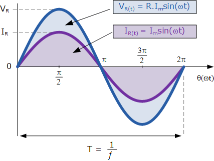
When the switch is in Off mode, an AC voltage (V) is applied to the resistor (R). This voltage can force the current to move. This current will increase and decrease as the main voltage rises and falls with a sinusoidal form. The voltage and current will both reach their peak amount or maximum because the load is a resistance, and back to zero value at precisely the same time, i.e., they improve and reduce simultaneously and are introduced as “in-phase”. Consider the diagram below.
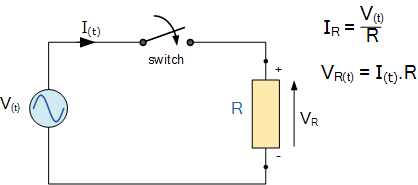
Then the electrical current that moves within the AC resistance changes in sinusoidal format with time and is presented by the frequency equation of I(t), where I is the maximum value of the current and θ is the coefficient of the phase angle. We can also present that for any special current, which is the flowing current within the resistor. So, the peak voltage or maximum in the terminals of R can be obtained by Ohm’s Law as:
V(t)=R.I(t)=R.{ I }_{ m }.sin(\omega t+\theta )
and the obtained amount of the current, i can be calculated:
{ i }_{ R(t) }={ I }_{ R(max) }.sin(\omega t)
So, for a particular resistive system, the alternating current in the resistor modifies related to the employed voltage through it following the equal sinusoidal format. As the basic frequency is equal to both the current and voltage, their phasors will also have the same values.
In other words, there is no phase shift between the voltage and current when applying an AC resistance. So, the current can obtain its minimum, maximum, and zero amount whenever the voltage achieves its minimum, maximum, and zero values in its sinusoidal diagram.
Sinusoidal Waveforms for AC Resistance
This “in-phase” influence can also be introduced by a phasor condition. Resistance is a real value in the complex domain meaning that there is no imaginary amount. Thus, as the current and voltage are both in the same phase with each other, there will be no phase shift (θ = 0) between them.
So, the vectors of each value are presented in super-imposed mode and are shown in the same reference axis. The transformation mode from the sinusoidal domain of time versus the phasor format can be obtained in the next section.
Phasor Diagram for AC Resistance
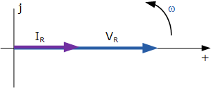
As a phasor provides the RMS amount of the current and voltage quantities dissimilar to the vector which presents the maximum or peak values, separating the peak amount of the time terms above by √2 the main current-voltage phasor equation is introduced as the RMS Relationship.
I=\frac { { I }_{ m } }{ \sqrt { 2 } } <\theta
V=\frac { R.{ I }_{ m } }{ \sqrt { 2 } } <\theta
R=\frac { V }{ I } =\frac { (R.{ I }_{ m })/\sqrt { 2 } <\theta }{ { (I }_{ m })/\sqrt { 2 } <\theta }
And the Phase Relationship can be obtained as follows:
V=R.{ I }_{ rms }<\theta
I={ I }_{ rms }<\theta
V<{ \theta }_{ v }={ I }<{ \theta }_{ i }
{ \theta }_{ v }={ \theta }_{ i }(in-phase)
This presents that a fixed resistance in an AC system generates an equation between its current and voltage phasors in the same method as it operates as the same resistors current and voltage diagram in a DC system. Although, in a DC diagram, this equation is typically named Resistance, as introduced by Ohm’s Law, in a sinusoidal form of AC diagram, this current-voltage relationship is now introduced as Impedance.
What is the Impedance?
In both AC and DC cases, this V-I diagram is usually linear in a fixed resistance. So, when applying resistors in AC systems, the Impedance with Z symbol is typically utilized to mean its resistance. As a result, we can correctly explain that DC resistance is equal to AC impedance for a resistor or Z = R.
The vector of impedance is provided by the letter (Z) for an AC system with the Ohm’s unit (Ω) as the same as for DC circuits. So, the Impedance can be evaluated as:
Z=\frac { V }{ I } \Omega 's
Impedance can also be introduced by a complex value as it is based on the frequency of the system, ω, when particular instruments are used. But in the form of a constant resistive system, this component is always zero and the final formula for impedance in this particular circuit will be:
Z=R+j0=\quad R\Omega 's
Because the phase shift between the current and voltage in a completely resistive AC system is zero, the power coefficient should also be zero. So, the power employed by the resistor can be evaluated by:
P=V.I={ V }_{ m }.sin(\omega t).{ I }_{ m }.sin(\omega t)={ V }_{ m }{ I }_{ m }{ sin }^{ 2 }(\omega t)
{ P }_{ max }={ sin }^{ 2 }(\omega t)\quad where\quad { P }_{ max }={ V }_{ max }{ I }_{ max }
Although, because the average power in a resistive system is based on the phase shift and in a fixed resistive diagram this is always zero, the power coefficient is equal to the average power used by the AC resistance and can be introduced by applying Ohm’s Law as:
{ P }={ V }{ I }={ I }^{ 2 }R=\frac { { V }^{ 2 } }{ R } \quad watts
which are equal to Ohm’s Law for DC systems. So, the effective energy used by an AC resistance is the same as the power utilized by the particular resistor in a DC system.
Many AC systems including heating circuits and lamps contain just a fixed ohmic resistance. In these circuits, we can utilize both Kirchhoff’s Law, Ohm’s Law, and simple circuit equations for evaluating and detecting the current, voltage, impedance, and energy like in DC system analysis. When operating with such methods, it is typical to employ RMS values.
Impedance Summary
In a particular resistance in AC circuit, the voltage and current are both “in-phase” as there is no phase shift in the system. The current flow within the resistance is straightly related to the voltage in it with the linear relation in the AC system which can be introduced as impedance.
Impedance, which is introduced by the Z sign, in a fixed resistance is a complex number including a real section that is the practical resistance value (R) and an imaginary zero section (j0). Therefore, Ohm’s Law can be applied in systems having an AC resistance to evaluate these currents and voltages.
Now, we can consider two circuits to better know the resistance vs. impedance subject.
In circuit (1), there is just one resistance part (R) attached to the AC supply. This resistance is the whole additional part of the circuit. The value of the instrument which controls the flow of current in an AC system is generally called impedance. So, an impedance of this circuit can be introduced as Z = R, and the imaginary value of this element is zero.
In circuit (2), current monitoring instruments are L, R, and C, and hence their junction, all together, can be assumed as impedance. The amount of impedance can be calculated by the Z = R + j(ωL-1/ωC) formula where (-j/ωC) and jωL are the capacitive and inductive reactance respectively. Due to the ω is equal to 2πf, the impedance value is based on the supply frequency.
Key Differences to Understand Resistance vs. Impedance
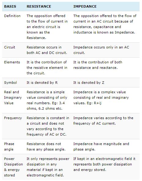
The key differences between resistance and impedance are explained below in brief details and with a comparison chart:
Resistance is used in an electrical diagram to control the flow of current. This current may be AC or DC. Regardless of the current form, resistance determines the flow of current.
Impedance is a general term for a combination of inductive reactance, resistance, or capacitive type of reactance. This means a complex of resistance and various types of reactance in different shapes and formats.
Resistance is utilized in both DC and AC systems, while impedance is employed just in an AC circuit.
Resistance is determined by (R) in the diagrams and equations, while impedance is presented by (Z).
Resistance is a specific value including only real numbers. For example, 5 ohms, 10 ohms, etc. But impedance includes both imaginary and real numbers. For instance: 5R+10ij, where 10R is the real value and 10ij is the imaginary section.
More than one resistances are added simply in a mathematical format. This means that if three resistances are R1, R2, and R3, then the total amount will be (R1+R2+R3). On the other hand, we cannot add two or more impedances by this method. They must be added vectorially.
The resistance value of the system does not modify based on the frequency of DC or AC, while impedance changes with the variation in frequency.
Impedances include both phase angle and magnitude, while resistance does not have phase shift in their structure.
If resistances have been kept in an electromagnetic field, they show power dissipation in any substance. Likewise, if the impedance is subjected to the electromagnetic system, it presents both energy storage and power dissipation.
Active power is utilized by resistance. In impedance, active power is used by the resistive section, and passive power is utilized by the inductive section.
The next figure shows a comparison chart in a brief format to understand the Resistance vs. Impedance subject more clearly.
Buy Equipment or Ask for a Service
By using Linquip RFQ Service, you can expect to receive quotations from various suppliers across multiple industries and regions.
Click Here to Request a Quotation From Suppliers and Service Providers
Read More On Linquip
- Difference between Capacitor and Inductor- Capacitor vs. Inductor
- Difference Between Condenser and Capacitor in a nutshell
- Mastering Resistance Calculations: A Comprehensive Guide for Electrical Enthusiasts
- Principal Difference Between Active and Passive Filters
- Difference Between Multimeter and Voltmeter
- Difference Between Potentiometer and Voltmeter
- Difference Between Voltmeter and Ammeter
- All Types of Pneumatic Fittings: Specifications and Applications
- A Useful Guide to Different Types of Inductors
- What is Time Division Multiplexing – TDM: A Basic Guide
- 7 Different Multimeter Parts and Components: All You Need to Know about All the Components
- The Complete Library Of Types Of Anemometer
- What Is Strain Gauge? A Short Story of An Electronic Device



I=\frac { { I }_{ m } }{ \sqrt { 2 } } <\theta ??? the way the formula's are written, is very confusing.
great post
Thanks for visiting our website, Zad! You can also visit our Industrial Equipment page, where you can find various pumps based on your application and demand.