Here we want to talk about a Kaplan turbine as one kind of reaction turbine. A reaction turbine is one sort of turbine that generates torque by reacting to the weight or pressure of a fluid. The operation of reaction turbines can be described by Newton’s third law of motion (i.e. action and reaction are balanced and reverse).
The Kaplan turbine is a full reaction turbine that operates by generating lift on the impeller blades owing to its aerofoil form. Kaplan Turbine is a key product for industrial and electricity purposes. Kaplan Turbines are available from a variety of suppliers and companies, as well as various Manufacturers and Distributors, and there are many Kaplan Turbines for Sale on Linquip.
There is a complete list of Kaplan Turbine services on the Linquip website that covers all of your needs. Linquip can connect you with a number of industrial Kaplan Turbine service suppliers and experts. Linquip can provide you with a list of Kaplan Turbine Specialists and subject matter experts who can help you test your equipment.
Despite an impulse turbine, the nozzles that discharge the working fluid, often water, are connected to the rotor in a reaction turbine. The acceleration of the fluid moving from the nozzles creates a reaction force on the pipes and makes the rotor move in the reverse direction. The pressure of the fluid varies while passing through the rotor blades.
A pressure casement is needed in most cases to hold the working fluid as it operates on the turbine; in water turbines, the casing also keeps the suction. Where a casing is not present, the turbine must be fully immersed in the fluid flow. Kaplan turbines follow the reaction turbine theory. It what follows, we want to talk about different aspects of a Kaplan turbine.
What is a Kaplan Turbine?
A Kaplan turbine is one kind of a propeller hydro turbine (particularly a reaction turbine) used in hydroelectric plants. Waterflow both in and out of Kaplan turbines through its rotational axis, which is called axial flow. The point that makes Kaplan turbines special is that the blades can change their demand to preserve maximum efficiency for various water flow rates. Kaplan turbine, similar to Francis turbine, is a reaction turbine. Water running through a Kaplan turbine loses its pressure.
The area that water can join these turbines is great, equal to the entire space that the blades fill. The large area of Kaplan turbines makes them most useful where large volumes of water flow can be used even in dams with a relatively low head. This is especially notable as previous to the Kaplan turbine development, most turbines were only proper for large heads of water.
These turbines should be designed to allow large amount of water to flow through them without damage. The way of designing Kaplan turbines is slightly different from other turbines. The Kaplan turbine is much more modest. There is a flow passage that injects water in the radial direction, and functional guide vanes – permanent blades that direct the water abruptly to enter the turbine in the axial orientation.
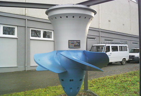
The turbine itself is provided with several rotor blades connected directly to the central shaft of the turbine. The blades are attached with adjustable joints so that the angle can be adjusted, ensuring the maximum efficiency is achieved for any given flow rate and water head.
It is necessary to note that this turbine’s blades are not flat. Instead, they rotate slightly because the blade’s exterior part moves more swiftly than the inside part.
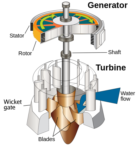
The way that water moves through a Kaplan turbine is somewhat different from other kinds of turbines. At first, the water is directed through the turbine radially, advancing from the side. This movement is done since the generator is typically located somewhere along the turbine’s rotation axis, so if the generator were found here, it would get wet. Preferably, the guide vanes rapidly carry the water through a ninety-degree turn to hit the blades axially. Rather than redirecting the water, these vanes are aligned to give the water an appropriate amount of “swirl.”
The water then moves down over the propeller’s blades, turning it with the “swirl” of the water. Therefore, this type of turbine is recognized in the class of reaction turbines as the reaction force from pushing the water on the propeller drives the propeller to move. The water moves out from the turbine axially.
More information about the operation of Kaplan turbines can be found here.

Watch Video About Kaplan Turbine
Main Parts of a Kaplan Turbine
We want to take a look at the main components of a Kaplan turbine as listed below. A Kaplan Turbine is comprised of:
- Scroll casing,
- Guide vane mechanism,
- Draft tube, and
- Runner blades
In what follows, we will discuss different parts of a Kaplan turbine.
Scroll Casing:
The scroll casing is a spiral specimen of a casing that decreases the cross-section area. At first, the water from the penstocks goes into the scroll casing and then goes to the guide vanes. The water turns through 90° From the guide vanes and flows axially over the runner. The scroll casing shields the runner, runner blades, guide vanes, and other interior parts of the turbine from external damage over the turbine.
Guide Vanes Mechanism:
Guide Vanes Mechanism is the unique, controlling part of the whole turbine, which opens and closes based on the power demand. When more power output is required, it opens more to let more water hit the rotor’s blades. And when the output required power is low, it closes to stop the flow of water. When the guide vanes are missing, then the turbine cannot work effectively; as a result, the efficiency of the turbine reduces.
Draft Tube:
At the outlet of the reaction turbine’s runner, the available pressure is generally smaller than the atmospheric pressure. So, the outlet water cannot be straight discharged to the tailrace.
A tube or pipe can gradually increase the area, and this is employed in water discharging from the turbine to the tailrace.
Thus, the expanding area of the tube or pipe is named a Draft tube. One end of this draft tube is attached to the runner outlet, and the opposite end is submerged beneath the level of water in the tail-race.
A significant point about this component is that the Draft tube is used only in the Reaction turbine.
Types of Draft Tube:
Four types of the draft tube are available as listed below:
- Simple Elbow Draft Tube
- Elbow with the varying cross-section
- Moody Spreading Draft Tube
- Conical Diffuser or Divergent Draft Tub

Working Principle of the Kaplan Turbine With Diagram
This turbine is one sort of axial flow reaction turbines. In this way, the working fluid, which is often water, changes the pressure while moving within the turbine and produces energy.
The power is the combination of both the kinetic energy of the flowing water and hydrostatic head.
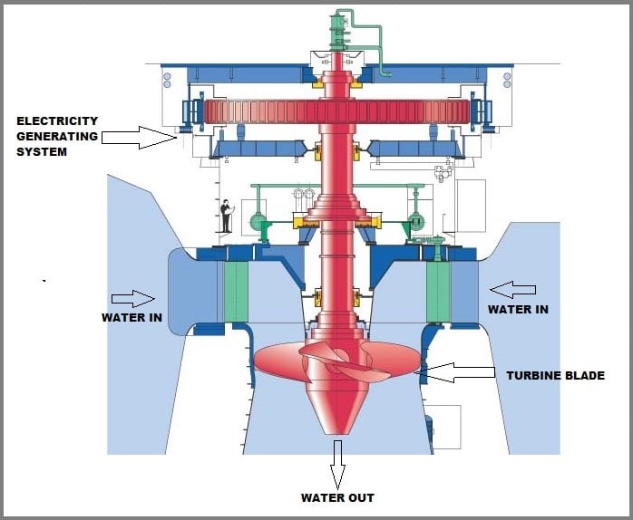
In order to understand the way it produces power, the water from the pen-stock enters the scroll casing. After that, the water passes through the scroll casing, and the guide vanes guide the water from the casing to the runner’s blades. The critical point is that the vanes are flexible and can adjust themselves based on the required flow rate.
While the water moves across the blades, it begins rotating because of the water’s reaction force. Besides, the blades in the Kaplan turbine are also adjustable. The water goes through the draft tube, where its kinetic energy and pressure energy decrease from the runner blades.
Actually, the kinetic energy converts into pressure energy here and results in enhanced pressure of the water. Eventually, the water is discharged to the trail race. The turbine’s rotation is utilized to rotate the shaft of a generator to produce electricity and some extra mechanical work. Below is the diagram of Kaplan Turbine:

Advantages of the Kaplan Turbine:
The mentioned Turbine has some advantages, which are listed here:
- The Kaplan turbine works more effectively at low water head and high flow rates in comparison with other kinds of turbines.
- This turbine is meagerer in size, so it requires less space comparatively.
- The Kaplan turbine’s construction is more manageable.
- Kaplan turbine has more efficiency compared to other types of hydraulic turbines.
Disadvantages of Kaplan Turbine:
Rather than all advantages, the mentioned turbine has some disadvantages, which are listed here:
- The shaft can only be positioned in the vertical direction.
- A large flow rate is required for its operation.
- The main demerit in the Kaplan turbine is the cavitation process. It often occurs due to pressure drops in the draft tube, although the use of the draft tube and proper material such as stainless steel for the runner blades can reduce the cavitation problem to a more considerable extent.
Applications of Kaplan Turbine:
Here some applications of this turbine are presented:
– Kaplan turbines are extensively used everywhere in the world to produce electric power.
– These turbines cover the lowest head hydro sites and are particularly suitable for extensive flow conditions.
– Economical microturbines are manufactured around the world for individual power production with just two feet of head.
– Large Kaplan turbines are individually designed for any site to operate at the highest potential efficiency, typically more than 90%.
– Kaplan turbines are costly to design, manufacture and install but run for decades.
Download Kaplan Turbine PDF
Read More on Linquip
- Differences between Pelton, Francis, and Kaplan Turbine
- What is Propeller Turbine? Types and Working Principles
- TG50 Industrial Gas Turbine for Sale
- Gas Turbine Blades & Buckets for Sale
- Nozzles & Shrouds Gas Turbine for Sale
- Rotor & Stator Blades Gas Turbine for Sale
- Combustion Components Gas Turbine for Sale
- Types of Turbines: Classifications and Types
- 6 Best Home Wind Turbines (Residential): A Practical Guide
- Open Cycle Gas Turbine: A Detailed Overview
- The 8 Best Home Wind Turbines in 2022


