What is Poppet Valve? Working Principle & Types – A poppet valve is a form of directional valve that replaces the standard spool with a ball and seat. You may not know it, but you use poppet valves on a daily basis when driving to work. Your automobile would not be able to run without poppet valves! (If you have a combustion engine, that is.)
⇒ View a List of Valves for Sale and Their Suppliers ⇐
What is A Poppet Valve?
A poppet valve (also known as a mushroom valve) is a type of valve that regulates the amount and timing of gas or vapor flow into an engine.
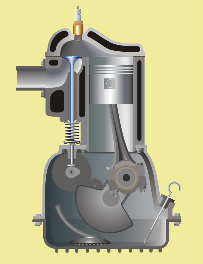
A hole or open-ended chamber, generally round or oval in cross-section, and a stopper, usually a disk form on the end of a shaft known as a valve stem, make up a valve stem. The valve face, which seals against a matching valve seat ground into the rim of the chamber, is sealed and is commonly ground at a 45° bevel. To keep the shaft aligned, it passes via a valve guide.
Pressure differentials on both sides of the valve might help or hurt its functioning. Higher pressure against the valve in exhaust applications helps seal it, whereas lower pressure in intake applications helps open it.
American E.A.G. Young of the Newcastle and Frenchtown Railroad devised the poppet valve in 1833. Young had copyrighted his invention, but all documents were lost in the 1836 Patent Office fire.

Design of a Poppet Valve
The poppet valve is fundamentally distinct from the slide and oscillating valves in that it raises from the seat with a movement perpendicular to the plane of the port rather than sliding or rocking across it to reveal a port. The fundamental advantage of the poppet valve is that it does not require lubrication because there is no movement on the seat.
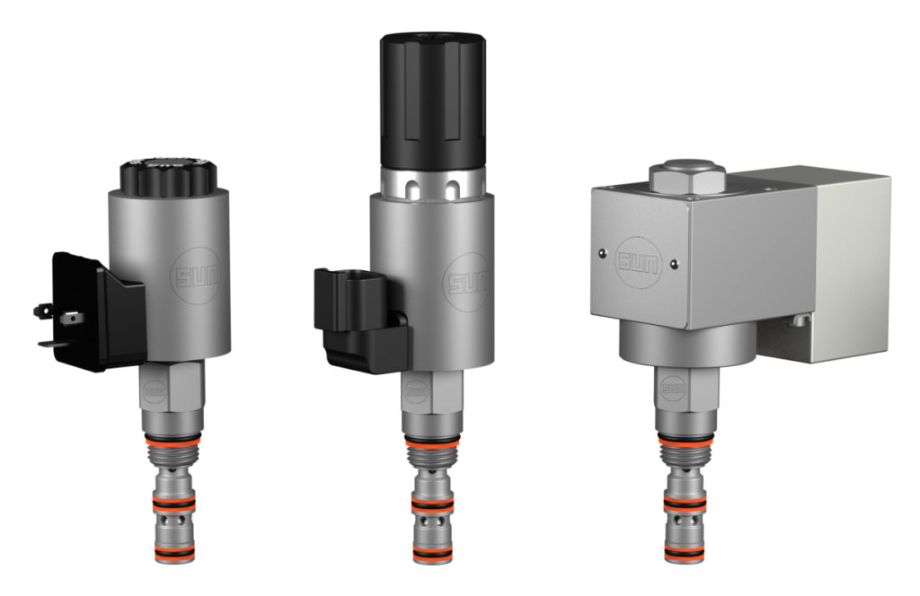
In most circumstances, a “balanced poppet” in a direct-acting valve is advantageous. Because all forces on the poppet are neutralized by equal and opposing forces, less force is required to move it. Only the spring force must be countered by the solenoid coil.
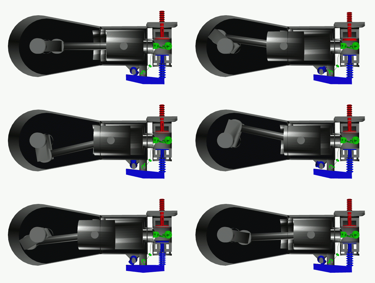
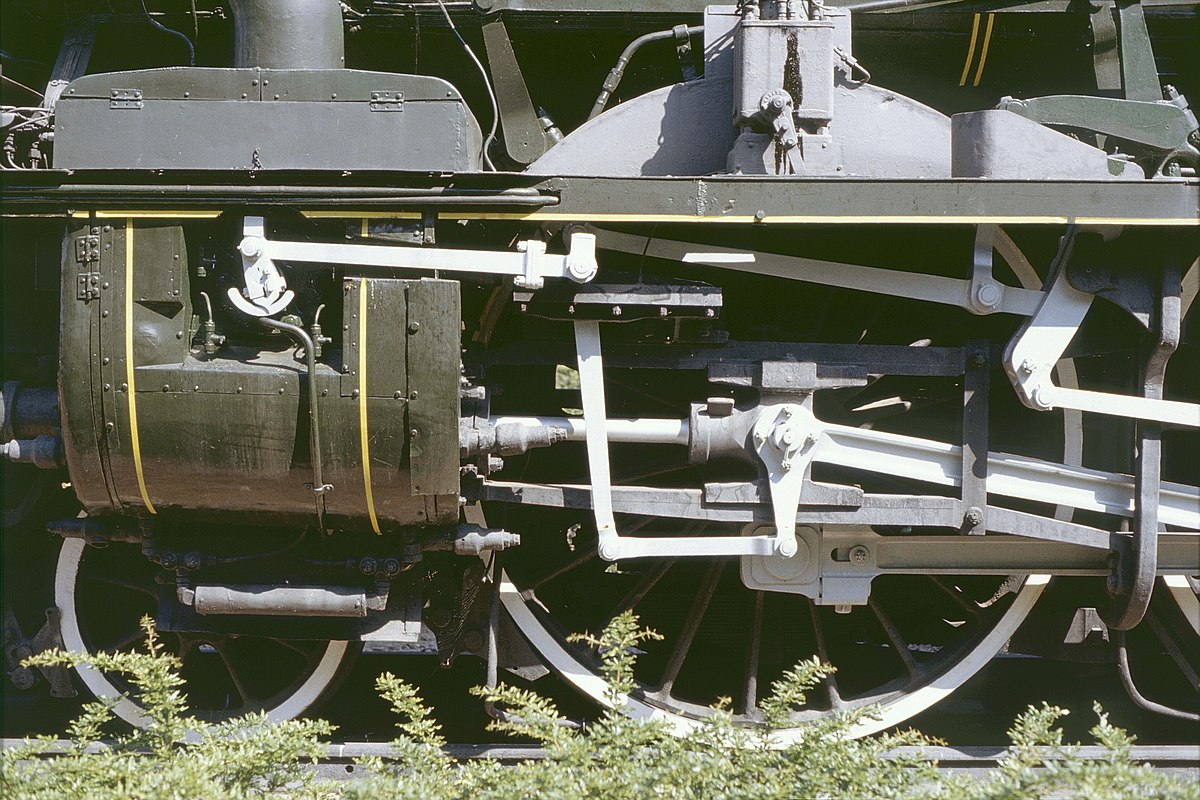
Poppet valves are most commonly associated with internal combustion and steam engines but they are also employed in a variety of industrial operations, ranging from regulating milk flow to separating sterile air in the semiconductor sector.
Poppet valves include the Presta and Schrader valves found in pneumatic tires. The Presta valve doesn’t have a spring and depends on a pressure differential to open and close during inflating.
Poppet valves are often used in the firing of torpedoes from submarines. Many systems employ compressed air to expel the torpedo from the tube, and the poppet valve recovers a considerable portion of this air (along with a significant volume of saltwater) to lessen the telltale cloud of bubbles that would otherwise reveal the boat’s submerged position.

Applications of Poppet Valves
With single-acting cylinders, poppet valves are widely used for load holding and load reduction. They’re employed in positive displacement pumps as unloading valves. In air tanks, they act as relief valves. A poppet valve is a simple solution to prevent flow reversal in a fluid circuit or to keep separate media from becoming contaminated in mixing systems.
Reverse flow is possible with some poppet check valves. A popular example is a hydraulic lift, where the check valve must allow fluid to flow into the cylinder while keeping the piston in place. Fluid must reverse its passage through the valve to lessen the burden. The poppet is lifted off its seat by external pilot pressure, allowing fluid to return to the valve through the outlet.

Poppet Valve Considerations
Poppet valves do not require lubrication, which might be advantageous when choosing valves for chemical compatibility with diverse fluids. This makes them ideal for medical gas delivery systems, as well as any other system that requires clean, dry air. In hydraulic systems, where the hydraulic fluid acts as a lubricant, lubrication is less of an issue, making spool valves viable. Poppet valves are self-cleaning because the huge relative valve opening creates a big flow across it, which sweeps any contaminants from unclean air away.
Spool valves, which need precision drilled valve bodies and machined spindles, are more expensive to manufacture. Duplicating a multi-way spool valve with numerous three-way poppet valves can be a cost-effective option, especially if the poppet valve’s other benefits—low wear, quick reaction, and so on—are considered.
Finally, some speculation as to the origin of the word “poppet”: these valves do not create a popping sound when they work, though other air relief valves may. More likely, the phrase came from an old term for a marionette (and was connected to “puppet”), which makes sense when one considers the engine poppet valves dancing on and off their seats, controlled from above.
Usage of Poppet Valves in Combustion Engines
Poppet valves regulate the flow of intake and exhaust gasses through the cylinder head and into the combustion chamber in most piston engines. The interior of the combustion chamber side of the poppet valve is a flat disk, while the other side tapers from the disk to a thin cylindrical rod known as the “valve stem.”
Materials and Durability
The valves in most modern mass-production engines are solid and constructed of steel alloys. To enhance heat transfer, some engines employ hollow valves filled with sodium.
The cylinder head of many contemporary engines is made of aluminum. Although this improves heat transmission, it necessitates the use of steel valve seat inserts, as opposed to the valve seats being a component of the cylinder head in previous cast iron cylinder heads. Because the valve stem has a gap of 0.4–0.6 mm (0.02–0.02 in), a valve stem seal is employed to prevent combustion gasses from escaping or oil from being sucked into the combustion chamber. A rubber lip-type seal is commonly utilized. A puff of blue smoke from the exhaust pipe is a frequent indicator of worn valve guides and/or poor oil seals when the intake manifold suction is raised, such as when the throttle is quickly closed.
There have been two significant concerns with valves in the past, both of which have been resolved thanks to advances in contemporary metallurgy. The first was that early internal combustion engines had significant valve wear rates, which necessitated regular valve jobs to regrind the valves. Second, since the 1920s, lead compounds have been used in gasoline (gasoline) to minimize engine banging and provide valve lubrication. Leaded gasoline was phased out in many industrialized nations by the mid-1990s, thanks to modern materials for valves (such as stainless steel) and valve seats (such as satellites).
Actuation Method
In the 1890s and 1900s, early engines featured an “automatic” intake valve that was opened by the combustion chamber vacuum and closed by a light spring. To open the exhaust valve against the pressure in the cylinder, it had to be manually operated. Automatic valves simplified the process although valve float reduced the engine’s performance, and mechanically driven inlet valves were increasingly used for vehicle engines from approximately 1905.
The valve is normally operated mechanically by pressing on the end of the stem, with the valve being returned to the closed position by a spring. The weight of the valvetrain means the valve spring cannot shut the valve rapidly enough at high RPM, resulting in valve float or valve bounce. Desmodromic valves employ a second rocker arm to close the valves manually (rather than utilizing valve springs) and are occasionally used to eliminate valve float in high-RPM engines.
The camshaft(s) controls the valve opening in most mass-produced engines via many intermediary processes (such as pushrods, roller rockers and valve lifters). The valve lift and timing of when the valves open are influenced by the geometry of the cams on the camshaft.
Number and Location of Valves
The valves on early flathead engines (also known as L-head engines) were positioned next to the cylinder(s) in an “upside-down” arrangement parallel to the cylinder. The twisting path of the intake and exhaust gasses had substantial downsides for the airflow, which limited engine RPM and might cause the engine block to overheat under continuous heavy load, despite the design’s simplicity and inexpensive cost. The flathead design developed into the intake over exhaust (IOE) engine, which was utilized in a variety of early motorcycles and automobiles. The intake valves of an IOE engine were moved immediately above the cylinder (as in subsequent overhead valve engines), but the exhaust valve was left beside the cylinder in an upside-down position.
The overhead valve (OHV) engine, in which the intake and exhaust valves are both situated immediately above the cylinder, has entirely supplanted these designs (with the camshaft located at the bottom of the engine). By the 1990s, OHV engines had mostly been replaced by overhead camshaft (OHC) engines. The valve locations are similar in OHV and OHC engines, however, OHC engines have the camshaft situated towards the top of the engine with the valves, and OHC engines have more valves per cylinder. In comparison to most OHV engines, which have two valves per cylinder, most OHC engines feature an additional intake and exhaust valve per cylinder (four-valve cylinder head). Some OHC engines, on the other hand, feature three or five valves per cylinder.

Conclusion
In this post, we have described the basics of poppet valves along with their working principle, types, applications, and their advantages. At Linquip, you can find numerous Valve Companies, along with various Service Providers and Distributors.
FAQs about Poppet Valves
1. How does a poppet valve work?
The orifice of a poppet valve is opened and closed by lifting and lowering a sealing surface onto the aperture. The valve is normally held in the closed position by an internal spring. The sealing surface rises off the orifice when the spring force is overcome and the valve opens.
2. What is a poppet check valve?
A poppet check valve has a disc as the checking mechanism (usually at the end of a “sleeve” or “stem”). It’s usually spring-loaded to aid seal the valve before reversing fluid flow. The hydraulic shock, often known as the water hammer, is eliminated.
3. What is a poppet valve in a hydraulic system?
Pneumatic and hydraulic systems both employ poppet valves. In their de-energized states, solenoids are typically used to control them, and they may be programmed to be either usually closed or normally open. They’re also employed as relief valves to protect against overpressure and as check valves to provide one-way flow.
4. What is the difference between poppet and spool valve?
Poppet valves, unlike spool valves, provide a direct flow channel to the output. As a result, there is a quick reaction time. Poppet valves only open as much as the flow through it requires, traversing the shortest distance possible to do so, increasing reaction time.
5. What opens a poppet valve?
Poppet valves typically consist of a flat metal disk with a lengthy rod known as the valve stem. The stem is used to open the valve by pushing it down, and a string is used to close it when the stem is not pulled on.
Buy Equipment or Ask for a Service
By using Linquip RFQ Service, you can expect to receive quotations from various suppliers across multiple industries and regions.
Click Here to Request a Quotation From Suppliers and Service Providers
Read More on Linquip
- What is Air Valve? Working Principles & Types (Clear Guide)
- What is Solenoid Valve and How Does It Work? 2022 Guideline
- What is Automatic Expansion Valve: A Basic Guide
- Strainer Valve: a basic guide to know it better
- What Is Actuated Valve? Working Principle & Types
- What Is Linear Valve? With Example, Working Principles & Types
- Valve Manifolds: Working Principles, Function & Diagram
- What is Balancing Valve? Working Principles,Types & Function
- What is Manifold Valve? With Function & Types
- What is Pilot Valve? Working Principle & Types (Complete Guide)
- What is Drain Valve? Working Principle, Types & Applications
- What are Coaxial Valves? Working Principles and Type
- What is Isolation Valve? Working Principle & Types
- What is Block Valve? Working Principle & Types


