The velocity head is a fundamental fluid mechanics concept representing the bulk motion, i.e. the fluid’s kinetic energy. It can also be transformed into the pressure that the fluid would obtain where it is to be held without any energy loss. The velocity head determines the foundation of other fluid engineering methods, such as the K-value process of expressing pressure loss within fittings.
This article explains the method of determining the velocity head of the flowing fluid. The velocity head employs units of length as a measure of the kinetic energy of the moving fluid.
Velocity Head & Discharge Pressure
A velocity head can be an essential part when measuring a pump’s discharge pressure in the domain. Besides, the bourdon tube pressure gauge measures pressure similar to a piezometer and measures, particularly static pressure. In some situations, the velocity head can contribute significantly to the TDH. A detailed comparison of the field test data to the manufacturer’s test curve is not possible if it is not considered.
The location at which a gauge reading is taken can significantly affect the actual pressure reading. It is not surprising for a centrifugal pump to be attached to a sized pipeline for low friction losses through a short length of pipe that is identical to the pump discharge size. If the discharge pressure is estimated in that section, it can be different from a larger diameter pipe measurement.
For instance, many pumps with 3-inch discharges can create flows of more than 700 gallons per minute (GPM), and 4-inch models can surpass 1,100 GPM. As a matter of fact, almost all pump sizes are capable of flows that present too high discharge velocities. When this happens, the velocity head becomes a critical component when measuring the total dynamic head (TDH).
Velocity Head Calculation
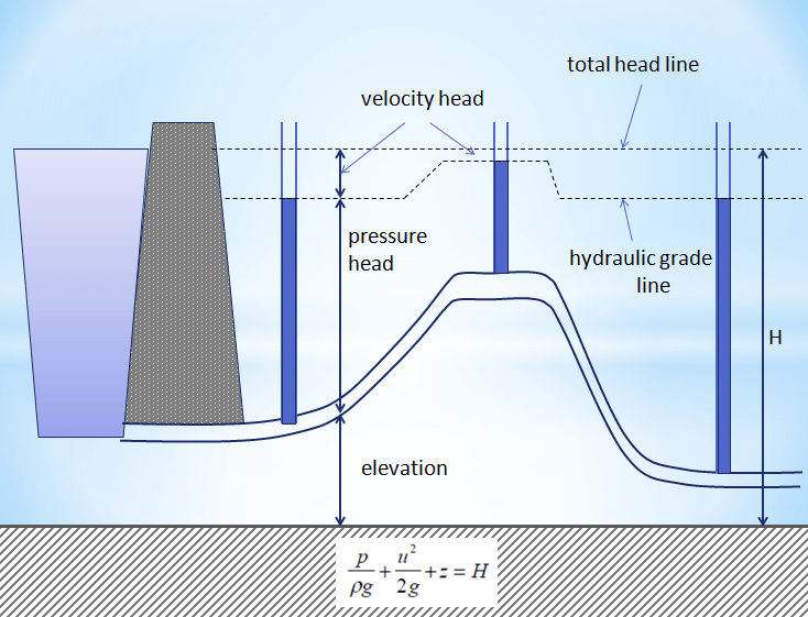
In fluid mechanics, the head is a concept that correlates the energy in an incompressible liquid to the height of an equivalent static column of that liquid. The units for all the various forms of energy in Bernoulli’s equation can also be measured in distance units. Hence, these terms are sometimes introduced as “heads” (velocity head, pressure head, and elevation head). The head is also determined for pumps. This head is regularly referred to as the static head and represents the maximum height (pressure) it can deliver. Therefore, the characteristics of all pumps can ordinarily be read from their Q-H curve (flow rate – height). Velocity and Pressure heads are demonstrated in the following figure:

Before proceeding to the calculation of the velocity head, the basic principles in fluid mechanics, Bernoulli’s theorem, should be explained.
Bernoulli’s theorem
Bernoulli’s theorem is one of the most applied equations in fluid mechanics. The theorem displays the conservation of energy in a flow system by linking velocity, pressure, and elevation. Its primary form is for an incompressible fluid with the inviscid flow:
\frac { { V }^{ 2 } }{ 2g } +\frac { P }{ \rho } +z=c
in which v is velocity, g is the gravitational acceleration, p is the pressure at the location, ρ is the fluid density, z is the elevation, and c is a constant in a unit of length. The term ½(v2/g) is regularly referred to as the velocity head and has units of the height of the streaming fluid. It can be thought of as the amount of potential energy needed to accelerate a fluid to its real flowing velocity. It also is the amount of head produced when fluid velocity falls to zero.
Nevertheless, pressure, by definition, is provided in force per unit area. Because the foundation for the simplified equation is incompressible flow, density is considered to be constant. Hence, multiplying both sides by ρ gives the common form:
\frac { { \rho V }^{ 2 } }{ 2g } +P+\rho z=\rho c=C
where C is in force per unit area, the term p + ρz combines the pressure head (p) plus the elevation head (ρz), which is designated as the dynamic head of the system.
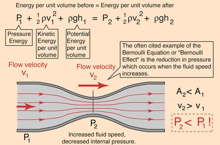
A schematic representation of Bernoulli’s equation is demonstrated below. Also, visualization of Bernoulli’s principle in terms of the head would be beneficial for understanding velocity and pressure heads, which this video can help you.

A simple example demonstrates the difference in these forms. For a fluid with ρ = 20 lb/ft3 and v = 10 ft/sec:
Velocity head = \frac { { V }^{ 2 } }{ 2g } =\frac { 1 }{ 2 } \frac { { { (10 }\quad \frac { ft }{ sec } ) }^{ 2 } }{ (32.2\quad \frac { ft }{ { sec }^{ 2 } } ) } =1.55\quad ft
Dynamic head = \frac { { \rho V }^{ 2 } }{ 2g } =\frac { 1 }{ 2 } \frac { (20\quad \frac { lb }{ { ft }^{ 3 } } ){ { (10 }\quad \frac { ft }{ sec } ) }^{ 2 } }{ (32.2\quad \frac { ft }{ { sec }^{ 2 } } ) } =31.06\quad \frac { lb }{ { ft }^{ 2 } }
Sadly, depending upon the application, the term velocity head may be assigned to the height of fluid, the pressure in force per unit area, or interchangeably. This can generate confusion; hence, always make sure of the definition being employed.
Engineering Toolbox has provided a very detailed and straightforward online calculator to measure dynamic pressure and velocity head, which you can find it here.
The Importance of The Velocity Head
Velocity head and conversion to static or pressure head have multiple engineering applications. For instance, let’s think about a distribution system. Fluid flows into a channel having many orifices to spread the liquid across an area. All fluid entering the channel must exit by the orifices. Our engineering evaluation and design assume uniform fluid distribution in many systems — but is that what we really get? How much will the distribution differ along the channel?

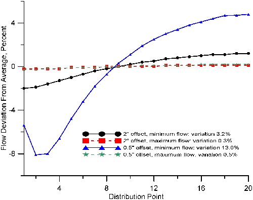
The above figure displays the results for two schemes of a distillation tower distributor. The first has orifices two inches above the channel floor. The second one has orifices a half-inch above the channel floor. At the minimum liquid rate, the fluid is two inches over the orifice, i.e., four inches above the channel floor for the first design and two and a half inches above the second floor. In both cases, the trough height sets the maximum flow rate.
it is desirable to restrain the variation between the high and low rates across all distribution points to no more than 3%. For high-quality distillation, this level of maldistribution is about as much as many systems can endure.
The distributor with the 2-in. offset from the bottom has a 3.2% deviation of flow from minimum to maximum. In opposition, the distributor with a 0.5-in. offset from the bottom has a 13% distinction in rates. This is because as the fluid progresses along the channel, its velocity drops. This makes the fluid rise, raising the elevation head available to drive the liquid through the holes. The minimum flow rate is close to the entry of liquid into the channel. At that point, velocity is highest, so the elevation head has been transformed into velocity.
The curve for the 0.5-in. offset at minimum flow exhibits a second-order impact. A head must build up adjacent to the inlet area to produce the velocity required. Then elevation diminishes as velocity rises and eventually goes up repeatedly as velocity drops. Maintaining track of these velocity gradients is the solution to making distribution systems work properly.
What’s of particular importance here is that if various channels are employed in parallel, the flow errors are systematic. Flow leads to get distributed to the channel ends, near the tower wall. This raises the consequences of maldistribution.
Conclusion
Piping systems perform in the same way. Many tank mixing systems utilize a pipe with openings to distribute feed into a container. At velocities found in many designs, thoughtful observation will prove the flow is completely distributed toward the back end of the pipe. If this is a dilemma, the pressure drop is typically the solution. Pressure drop is a remarkably efficient distribution device in piping systems.
Velocity head can be an essential factor when examining pumps in the field. At a flow velocity of 8 feet per second, the velocity head is just 1 foot, but it grows exponentially with any flow velocity increase.
Understanding simple but necessary fundamentals often is the key to a flawless operation. The critical basis here is the interaction of velocity, head, and elevation.
Buy Equipment or Ask for a Service
By using Linquip RFQ Service, you can expect to receive quotations from various suppliers across multiple industries and regions.
Click Here to Request a Quotation From Suppliers and Service Providers
Read More on Linquip
- Turbo Types: Classifications and Examples
- Hydraulic Head: All You Should Know About it
- The Complete Library Of Types Of Anemometers
- All You Need to Know about Transducer
- The efficiency of Fuel Cell: Calculation Formula & Equation
- What is an Electrolytic Capacitor?
- What is Redox Flow Battery?
- Types of Electric Circuits: All Classification with Application
- What is Rotary Potentiometer? What It Does for Us


