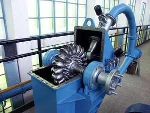
Generally, Hydro turbines are classified into two groups based on how the energy is exchanged between the fluid and the turbine: impulse turbines and reaction turbines. Hydro turbines are installed to convert the potential energy and kinetic energy of water flow into mechanical work.
Impulse turbines are described as turbines in which high-velocity jets of water or steam collide with the turbine blades to rotate the turbine and generate energy. The impulse turbine gets its name from the impulse force generated by the water jet’s hitting blade. Several Suppliers and Companies, as well as other manufacturers and distributors, supply impulse turbines, and there are several Impulse Turbines for Sale on Linquip.
There is a comprehensive list of impulse turbine services on the Linquip website that meets all of your needs. Linquip can connect you with a number of industrial impulse turbine service suppliers and experts who can help you. Linquip has a team of Impulse Turbine Experts ready to help you test your equipment.
Impulse turbines operate based on the change of velocity vectors. In general, the potential energy of the water (or another fluid, e.g., steam) based on the height of the waterfall is converted into kinetic energy by one or more nozzles and then water hits the turbine blades at high speed causing the turbine to spin and consequently generates electricity. These turbines are more suitable for extracting energy from the high head and low flow conditions.
Why Is It Called an Impulse Turbine?
The Pelton turbine is an impulse turbine, as opposed to other types of turbines that are reaction turbines. This simply implies that rather than moving as a consequence of a reaction force, water causes the turbine to move by creating an impulse.
Working Principle of Impulse Turbine
In these turbines, the static pressure inside the runner is constant, and the turbine runner is at atmospheric pressure. The runner spins in the air, and the fluid is sprayed to the blades through the nozzle to exchange energy with the turbine. A jet nozzle or a series of nozzles directs the high-speed flow to the blades, which are usually in the shape of buckets or cups. Therefore, only pressure changes occur in the nozzles.
The application of the curved blades is to change the velocity of the flow. This strike causes a change in momentum and based on the law of conversation of energy, a force is applied to the turbine blades. According to Newton’s second law of motion, the force obtained through the motion of a fluid depends on two factors: the mass of the fluid entering the turbine and the changes in fluid velocity between the turbine inlet and outlet. Since no change in fluid mass occurs, only velocity changes are taken into account in calculating the force applied to the runner.
Thus, in the power generation process in impulse turbines, the following steps are implemented.
- The stored water flows from a source upstream through Penstock to be delivered to the nozzle.
- The potential energy of the water inside the nozzle is converted into kinetic energy and injected into the blades or buckets; thus, the runner spins.
- There is a mechanism to control the flow of water injected into the runner. The spear usually plays an important role in this process.
- The generator attached to the shaft converts mechanical energy into electrical energy.
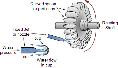
Impulse turbines have the ability to take all the kinetic energy from the water for high efficiency. Water is discharged into the atmosphere from the bottom of the turbine housing after reaching the runner; therefore, there is no suction at the bottom of the turbine. Here you can see schematically how an impulse turbine works in the process of extracting power from the kinetic energy of water as well as its components.
Components of an Impulse Turbine
Impulse turbines are composed of the following components.
Runner
The runner consists of a circular disk to which a number of curved blades are attached and a cylindrical shaft in the center. Shafts and runners are usually made of stainless steel. In cases where the flow head is less, the runner is made of cast iron.
Buckets
Buckets are a set of spoon-shaped cups that are mounted around the runner to exchange energy between the fluid and the turbine. The fluid jet hits these buckets after leaving the nozzle, making the turbine to rotate and exiting the outer edge of the bucket. The change in the direction of the fluid during the exit compared to the angle of impact varies depending on the design of the turbine.
To get the largest momentum, this angle must be 180 degrees. However, this angle is limited to angles of about 170 degrees due to considerations such as that the exit flow from one bucket does not collide with the next bucket and does not cause it to brake. These buckets are made of stainless steel or cast iron.
Nozzle
The nozzle is installed to adjust and jet the fluid flow to strike the buckets. As mentioned earlier, it is the only part of the impulse turbine assembly that the pressure changes and the flow head are converted into kinetic energy. The volume of water jet reaching the buckets is adjusted by a component called a spear, which is a conical needle that moves in and out of the nozzle by a hand wheel or automatically. By moving this needle backward, the water flow increases, and by moving forward, it decreases.
The nozzle is typically made from tungsten carbide, which is very hard and can withstand erosive particles.
Casing
The casing for an impulse turbine is a shield over the turbine to prevent the water from splashing and also to guide it to the spillway, which exists for the extra water to protect the structural integrity of the dam. Normally, Cast iron is used to manufacture the casing.
Penstock
Penstocks in hydropower plants are pipes and channels that carry water from dams and reservoirs to turbines. In general, they are made of steel. Water flows in these ducts under high pressures.
The figure below shows the different components of impulse turbines and their positions.
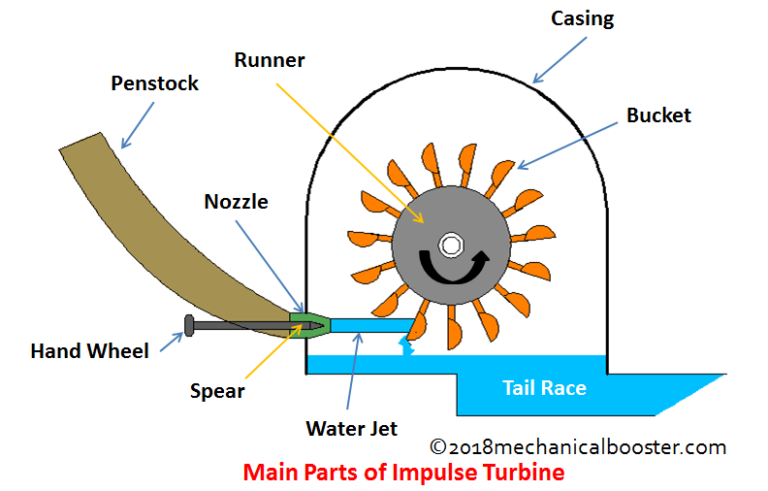
In addition to the main components mentioned above, a mechanism is usually used to prevent the turbine from rotating. When the water jet is stopped, the runner continues to rotate due to the effects of inertia. In these cases, to prevent this rotation, a jet of water is injected into the back of the buckets, which is called a breaking jet.
Here you can schematically see how an impulse turbine works in the process of extracting power from the kinetic energy of water as well as its components.
Impulse Turbine Types
Water turbines that are mostly used in hydropower plants are:
Pelton
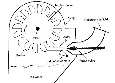
Pelton turbine consists of three main parts: nozzle, runner, and deflector.
This turbine is used for high water drop heights. The water head is converted to high-speed flow by one or more nozzles (up to 6). Water flow and, consequently, the power of the turbine are controlled by the spear by regulating the water flow quantity.
A series of buckets are installed symmetrically around the cylindrical runner of the turbine. The special shape of these buckets causes the water jet to hit the center of the bucket (splitter) and comes out from both sides. This exit is such that the water coming out of the bucket does not hit the next one and does not lead to brake. The axis of the turbine wheel can be placed horizontally or vertically. For high powers and a higher number of nozzles, the shaft is always vertical, and the generator is installed above the turbine.
The deflector is located between the runner and the nozzle, and its task is to prevent water from spraying from the nozzle to the buckets when the load is suddenly removed from the turbine, and its rotational speed is increased. Then, gradually with the help of a spear, the flow of water stops. It is also worth mentioning that due to the possibility of the occurrence of the water hammer phenomenon, the water velocity in the nozzle cannot be reduced quickly, and the discharge can be cut off.
The following figure shows a schematic of the Pelton turbine and other components related to the operation.
Here are some other hydraulic and physical features:
- It is utilized for heads between 20 meters to hundreds of meters and discharges between 5 to 1000 liters per second.
- Pelton turbine installation is generally easier than a reaction turbine, like Kaplan, with similar power because piping requirements are small due to relatively low flow rates.
- Due to the operation of the Pelton turbine at high water pressures, the equipment required for Penstock in these turbines is complex and expensive.
- Pelton turbines can achieve up to 95% efficiency; Maximum efficiency of 90% is attainable in micro-scale hydropower plants.
To learn more about the history and hydrodynamic principles of the operation of the Pelton turbine, visit here.
Turgo
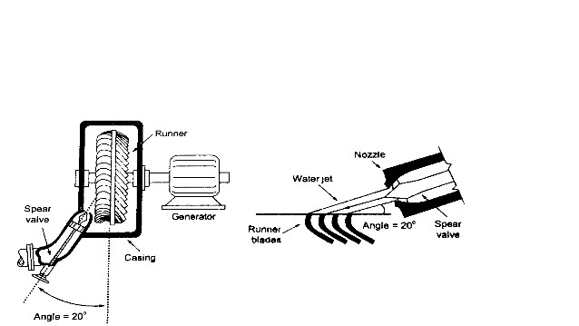
Turgo turbine is another type of impulse turbine that operates similar to Pelton; the difference is that in these turbines, the water jet hits the buckets obliquely (about 20 degrees). Because of the complicated shape of the buckets, it is more difficult to manufacture the buckets. Turgo turbine has a higher specific speed than Pelton. The advantage is having a larger jet and a smaller machine size compared to Pelton for equal power. This type of impulse turbine is used in small hydropower plants.
You can see a view of the Turgo turbine and the position of the nozzle relative to the buckets in the figure below.
Some other physical features are listed here:
- They can have higher flow rates than Pelton turbines of the same physical size.
- They are proper for high rotational speeds.
You can learn more about Turgo Turbine in this video.
Cross-Flow
This turbine is a modified type of impulse turbine used in small hydropower plants. Like other types of impulse turbines, the rotor is rotating in air and is not fully submerged like a reaction turbine. One of the significant advantages and features of this turbine is that it can operate in a wide range of flow rate, head, and consequently power. In addition, it can adapt well to changes in flow while saving efficiency. A special control system can adjust the active part of the turbine according to the amount of water flow.
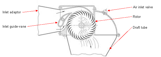
The different parts of this turbine are shown in the following figure. The runner is drum-shaped. In cases where the head is low, the runner is long, and vice versa, the higher head, the shorter runner. The water enters the turbine after passing through the inlet adaptor and guide vanes, which play the guiding role by leading the flow to hit the rotor at a suitable angle for gaining the best efficiency. The water leaves the turbine through the outlet pipe after passing through the runner twice; it first flows on the upper rotor blades and then returns through the center of the rotor and the lower blades, producing torque in both processes. This is why the name Cross-flow is applied to these turbines. Finally, the flow leaves the rotor through the draft tube. Water can enter the runner horizontally or vertically. The number of blades varies between 10 and 34.
Some other hydraulic and physical characteristics are:
- This turbine can be used for a head between 2 to 200 meters and a flow rate of 20 to 2000 liters per second.
- The power range of these turbines for hydro sites with typical power output is from 5 kW to 100 kW, and in large systems can be up to 3 MW.
- They are easy to fabricate and need nearly little maintenance.
More information about Cross-flow turbines can be found here.
Download Impulse Turbine PDF
Buy Equipment or Ask for a Service
By using Linquip RFQ Service, you can expect to receive quotations from various suppliers across multiple industries and regions.
Click Here to Request a Quotation From Suppliers and Service Providers
Read More On Linquip
- Types of Turbines: Classifications and Types
- Draft Tube: A Basic Guide to The Types, Function, And Efficiency
- What is Propeller Turbine? Types and Working Principles
- Difference between Impulse and Reaction Turbine
- Spare Parts Gas Turbine for Sale
- Taurus 60 PG Industrial Gas Turbine for Sale
- 6B.03 Gas Turbine for Sale
- TG20 Industrial Gas Turbine for Sale
- Combined Cycle Gas Turbine
- Efficiency of Wind Turbines
- What is Low Head Turbines?
- What is Tesla Turbine and How Does it Works?
- Hydrogen Gas Turbine: All You Need to Know
- What is Hydrokinetic Turbines? Working Principles and Output Power
- What is Propeller Turbine? Types and Working Principles
- Beginner’s Guide: The Difference Between Gas Turbine and Gas Engine
- The Practical Guide To The Difference Between Gas Turbine and Steam Turbines
- How Do Wind Turbine Generators Work?
- How Does a Steam Turbine Work? A Simple Descriptive Guide
- Steam Turbine Parts: A Comprehensive and understandable Introduction to All Components
- Pelton Wheel | Parts, Types, Working Principle and Efficiency
- Types of Propellers, Historical Development, and The Ways of Their Construction
- How Fast Does a Wind Turbine Spin? The Surprising Answer
- What is Kaplan Turbine? Diagram and Working Principles
- Cross-Flow Turbine: Working Principle, Components, and Advantages
- Draft Tube: A Basic Guide to The Types, Function And Efficiency
- Gas Turbine Cycle: Everything You Need to Know About Gas Turbine Working Principle
- What is Wind Turbine? The Short and Essential Answer

