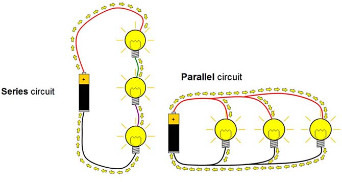
The main difference between series and parallel circuits is based on the arrangement of the parts in the circuit. Several components are joined together in a series circuit with a cascaded orientation which means that the top of a part is attached to the end of the other. However, in a parallel circuit, the dissimilar parts are combined in the head-to-head format and end to end arrangement.
What are Series and Parallel Circuits?
Circuits including only one resistance load and one battery are very easy to explore, while they are not typically found in actual applications. We usually employ circuits where more than two systems are joined together. There are two fundamental methods to combine more than two parts of the circuit: Series and Parallel formats. It is very essential to understand the difference between series and parallel circuits in electrical engineering and electronics technologies.
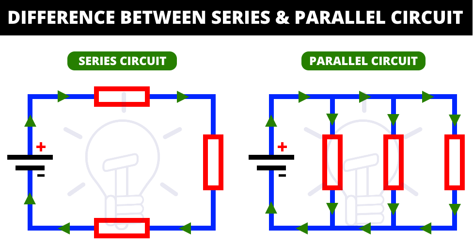
They are the most common formats of electrical systems and the other one is the parallel-series system, which is the junction of both, which can also be explored by using the same methods. Before discussing the difference between series and parallel circuits issue, we should discuss what an electrical system is and what are the basic parts of an electrical circuit.
Electrical Circuit
An electrical network or circuit is a closed system that supplies a special path to the current flow. It is an arrangement that combines various electrical parts like power source, capacitors, resistor, and inductor. It begins and finalizes at the same part creating a loop-like array. A circuit includes three basic components; Electrical components or Loads, A power source, and some conductors or wires for the relation between them. If you want to explore more about what an electrical circuit is, visit here.
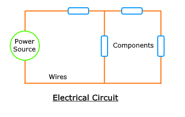
The Electrical parts are usually capacitors, resistors, inductors, and the load joined with the power section. Different kinds of electrical parts can influence the features of the circuit. The power section is what supplies the system and permits the production of current into the device. A power section may be a current source or a voltage source. The usual example of a power source is a battery.
The wires are particular conductors joining the electrical parts and the power section together. Combining the parts in different arrangements also changes the circuit characteristics including Parallel, Series, and Series-Parallel systems.
The Basics of Series and Parallel Connections
The main two kinds of connections are the Series and Parallel configurations. So, we should explore more about what a series and parallel format of connection are before discussing about the difference between series and parallel circuits.
Series Connection
A series connection between parts is when two or more than two sections are combined in a cascaded shape or the end of the 1st part is connected to the top of the next one. Series connection creates a special structure like a single line.
Parallel Connection
A connection is introduced as a parallel connection if two or more than two sections are combined side by side or their tops are joined together and their ends are connected as the same rule. The parallel connection creates multiple loops or paths.
What is a Series Circuit?
A circuit is known as a series circuit when all the parts in the system have the same current flow. In these circuits, the current has only one way. The household’s wonderful string lights are a common example of a series circuit. This is just a series of various tiny bulbs joined in series form. If one bulb is broken, all the other bulbs do not continue their operation.
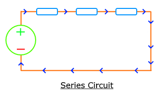
Series Circuit Definition
A circuit is defined as a series circuit if the parts are joined in a series formation or cascaded configuration in a straight line. A series circuit creates an array that has just one path, therefore, the current flows through parts with the same value and the voltage divides according to the resistance of each section.
Current in Series Circuit
The current-flow through each part in a series system remains the same. It can be calculated by the current supply of the power section. Because there is just one way for the current flow, the current cannot divide.
Voltage in Series Circuit
The amount of the voltage reduces across each part in a series system that is related to the supply source of voltage. This voltage in a series system divides between the parts due to their resistance value.
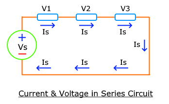
So, the voltage reduces across each part is different and cannot be divided equally.
{ V }_{ T }={ V }_{ 1 }+{ V }_{ 2 }+{ V }_{ 3 }+...+{ V }_{ n }
Resistance in Series Circuit
When resistors are joined in a series arrangement, their total value increases and it is the sum of each resistance of separate resistors.
{ R }_{ eq }={ R }_{ 1 }+{ R }_{ 2 }+{ R }_{ 3 }+...+{ R }_{ n }
As a result, the whole resistance in a series system is typically more than its individual ones.
Capacitor in a Series Circuit
When capacitors are joined in series format, their total capacitance reduces due to the voltage difference of each capacitor. The charge stored based on this voltage also drops.
\frac { 1 }{ { C }_{ eq } } =\frac { 1 }{ { C }_{ 1 } } +\frac { 1 }{ { C }_{ 2 } } +\frac { 1 }{ { C }_{ 3 } } +...+\frac { 1 }{ { C }_{ n } }
The whole capacitance in a series system is often less than the individual values.
Inductor is Series Circuit
The whole inductance of two or more than two inductors in a series system is the sum of individual values.
{ L }_{ eq }={ L }_{ 1 }+{ L }_{ 2 }+{ L }_{ 3 }+...+{ L }_{ n }
The whole inductance rises and it is always higher than the individual values in a series circuit.
Fault in Series Circuit
The total circuit does not operate properly if there is any fault in any part of the series circuit. Because the current supply damages and there is no other way for this current to move. So, a single fault in a small part will cause the whole circuit to harm. In order to revise a fault in a series circuit, you should check each part. Thus, the troubleshooting process for a series system is more difficult than a parallel one.
Power Supplies in Series Circuit
If two or more than two power supplies are combined in series format, their equivalent value will be the sum of separate ones while the total current provided will remain equal to the current provided by the individual source. You can employ the next electrical equations to evaluate the power of a series circuit:
P={ I }_{ 2 }{ R }_{ 1 }+{ I }_{ 2 }{ R }_{ 2 }+...+{ I }_{ 2 }{ R }_{ n }
Or
P=\frac { { V }_{ 12 } }{ { R }_{ 1 } } +\frac { { V }_{ 22 } }{ { R }_{ 2 } } +...+\frac { { V }_{ n2 } }{ { R }_{ n } }
So, if you want to improve the voltage of the power source, you should use the series format. For example, two 12v batteries joined in the series form will present 24V of the whole voltage.
What is a Parallel Circuit?
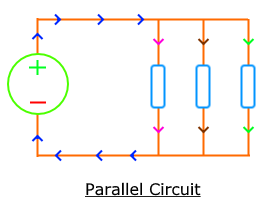
A circuit is introduced as the parallel circuit when the electric current has different ways to flow through the system. The parts placed in the parallel systems will have a fixed voltage in their ends.
Parallel Circuit Definition
A circuit is defined as a parallel circuit if the electrical parts are joined in a parallel arrangement or their ends are combined in a specific point. It creates different pathways or loops for the current to move.
Current in Parallel Circuit
The current in a parallel circuit separates and reduces through each section. Therefore, the whole current or supply part is evaluated by the sum of the values through individual parts and it is based on the amount of their resistance.
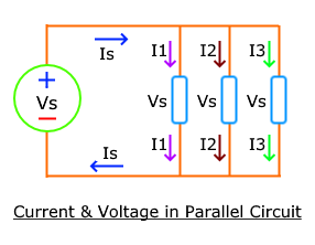
{ I }_{ T }={ I }_{ 1 }+{ I }_{ 2 }+{ I }_{ 3 }+...+{ I }_{ n }
Voltage in Parallel Circuit
The voltage of the parallel circuit remains constant within each path or part because each section is joined to the supply at a particular point.
{ V }_{ T }={ V }_{ 1 }={ V }_{ 2 }={ V }_{ 3 }=...={ V }_{ n }
Resistors in Parallel Circuit
The whole resistance of several resistors in the parallel circuit reduces and it is normally less than the individual values.
\frac { 1 }{ { R }_{ eq } } =\frac { 1 }{ { R }_{ 1 } } +\frac { 1 }{ { R }_{ 2 } } +\frac { 1 }{ { R }_{ 3 } } +...+\frac { 1 }{ { R }_{ n } }
Capacitance in Parallel Circuit
The whole capacitance of capacitors designed in the parallel circuit improves and it is equal to the sum of the values of the individual capacitors.
{ C }_{ eq }={ C }_{ 1 }+{ C }_{ 2 }+{ C }_{ 3 }+...+{ C }_{ n }
This equivalent value is normally higher than the individual ones.
Inductance in Parallel Circuit
The whole inductance of the parts combined in the parallel circuit reduces and it is always less than the inductance value of the individual ones.
\frac { 1 }{ { L }_{ eq } } =\frac { 1 }{ { L }_{ 1 } } +\frac { 1 }{ { L }_{ 2 } } +\frac { 1 }{ { L }_{ 3 } } +...+\frac { 1 }{ { L }_{ n } }
Power supplies in Parallel Circuit
The total voltage of the system remains constant when power sources are combined in a parallel arrangement, while their whole current provided is the sum of current values of an individual power source. The next equations can be utilized to estimate the power in the parallel system:
P=\frac { { V }_{ 2 } }{ { R }_{ 1 } } +\frac { { V }_{ 2 } }{ { R }_{ 2 } } +...+\frac { { V }_{ 2 } }{ { R }_{ n } }
Or
P={ I }_{ 12 }{ R }_{ 1 }+{ I }_{ 22 }{ R }_{ 2 }+...+{ I }_{ n2 }{ R }_{ n }
Fault in Parallel Circuit
If there is a single fault in any part used in the parallel circuit, the other sections still operate properly, because there are various loops for the current to move. It is simpler to explore components in the parallel system because it is easier to detect the section having the problem.
The devices of your homes are combined in the parallel circuit. Because the voltage does not reduce between the sections and if any of them stop the function, it does not influence any other devices. So, it is easier to discover where the problem is.
Difference Between Series and Parallel Circuits
The main difference between series and parallel circuits is the value of current that moves through each of the sections in the circuit. In the series systems, the equal value of current flows in all the parts located in the circuit. Otherwise, in the parallel arrangements, the parts are set in a parallel form with each other and the circuit separates the current flow. The current provided from the supply will be reduced by the current flowing through each of these parts based on the value of their resistance.
Key Differences Between Series and Parallel Circuit
The key difference between series and parallel circuits is mentioned here briefly:
- The parts in a series system are placed in a single loop from one component end to another one. While the various sections in the parallel circuit are designed in different paths by the two terminals of the power source. One common example of a parallel circuit is the setup of a generator and a rotor.
- A constant current moves through all the parts of the circuit in a series form, whereas in a parallel configuration, a different value of current is flowing through each parallel loop of the system.
- Various voltage exists within each part of the series circuit, while in the parallel system, the constant voltage exists in the different components of the diagram.
- A single fault in one of the parts of the series system causes a big broken in the function of the circuit completely. On the other hand, a fault in a section of the parallel configuration does not affect the operating of another part of the system.
- The detection of a fault in the parallel circuit is too easy, but it is quite difficult in series circuits.
- The total resistance in a series circuit is typically greater than the biggest value of resistance in the connection, while the whole resistance in the parallel system is often less than any of the individual values in that combination.
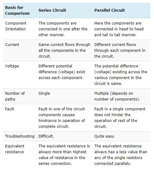
The next figure presents the full comparison to show the difference between series and parallel circuits.
Conclusion
So, from this post, we can infer that, in the series arrangement, the flowing current remains constant to the same at each component of the system. Whereas in the parallel circuits, the voltage within the two endpoints of the loops is the same as the voltage source.
In a series circuit, all parts are attached end-to-end, creating a single loop for current flow, while in a parallel configuration, all parts are attached across each other, making precisely two sets of common points. A branch in a parallel arrangement is a way for electric current created by one of the load parts like an inductor.
Buy Equipment or Ask for a Service
By using Linquip RFQ Service, you can expect to receive quotations from various suppliers across multiple industries and regions.
Click Here to Request a Quotation From Suppliers and Service Providers
Read More on Linquip
- What Are Resistors for LED Circuits? (Clear Guide)
- Generator vs Inverter: What’s the Main Difference
- What is Parallel Circuit? Definition & Example
- Types of Electric Circuits: All Classification with Application
- Differences Between P-Type and N-Type Semiconductor
- What is Series Circuit? Definition & Example

