What is a Series Wound DC Motor? A series wound DC motor like in the case of compound wound DC motor or shunt wound DC motor, falls under the classification of self-excited devices, and it gets its name from the fact that the field coil, in this case, is connected internally in series arrangement to the armature coil. Therefore, the field winding is exposed to the whole armature current unlike in the case of a shunt device.
What is a Series Wound DC Motor?
It seems impossible to live in a world without electric devices. Everything used in daily life, household appliances, car, even the wall outlets that give us continual electric current – would not be here if it weren’t for these mainly useful devices.
Thanks to the improvements of the 19th century and beyond, we can transform electricity into beneficial mechanical motion to implement all formats of amazing tasks. This post will focus on DC motors, one of the main electric motor forms and how it still benefits us in our applications. We will particularly investigate the series wound DC motor (sometimes introduced as the “series DC motor”), which is similar in almost all features to other DC motor types but has some important unique characteristics.
This post aims to help viewers know the series wound motors, how it performs and what kinds of applications benefit from this rugged electric device.
Brushed DC Motor: A Comprehensive Explanation of Working Principle, Parts, and Types
Working Principle of a Series Wound DC Motor
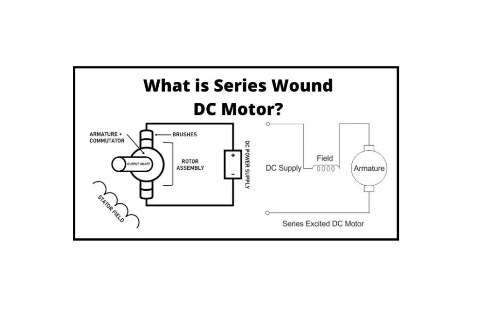
In most aspects, the series wound DC motor is similar to other forms of brushed DC motors in structure and performance. It is composed of two vital parts, the rotor and stator, which interact magnetically and electrically to create rotational movement on an output shaft. The main structure of DC motors is comparatively simple, and a simplified circuit diagram of them is presented below:
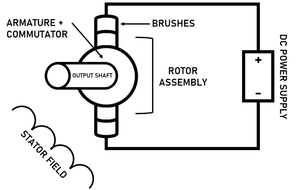
This is also the basic circuit diagram of all DC motors. This diagram is purposefully vague as to where the stator placement is in relation to the armature. So, its location and the power supply are the basic differences between various DC motors.
As presented, the stator field operates on the entire rotor assembly by generating a constant magnetic field; this field can be produced through a permanent magnet or an electromagnet constructed of wire winding (introduced as a “field winding”, as shown in the diagram). A DC power supply is attached to brushes that run the rotor, which is the rotating assembly that includes the armature, commutator rings, armature windings, and output shaft.
The armature consists of metal laminations that house the armature winding, which is around the main shaft. This is a particular coil of conductor wire that is looped across the armature windings and terminates at the commutator section.
The armature, when energized by pinching the brushes onto the commutator section, operates as an electromagnet and generates its own magnetic field just as the field winding performs. As the operator uses the DC power source, the current runs across the brushes, within the commutator loops, and into the armature coils, where the field of the armature will start to oppose the fixed magnet field of the stator. The rotor then “repels” itself away magnetically from the stator flux, but as it can only rotate in place, it results in useful mechanical output on the main shaft.
Knowing this information about typical DC motor performance, figure below now presents the specific configuration of a series wound DC motor:
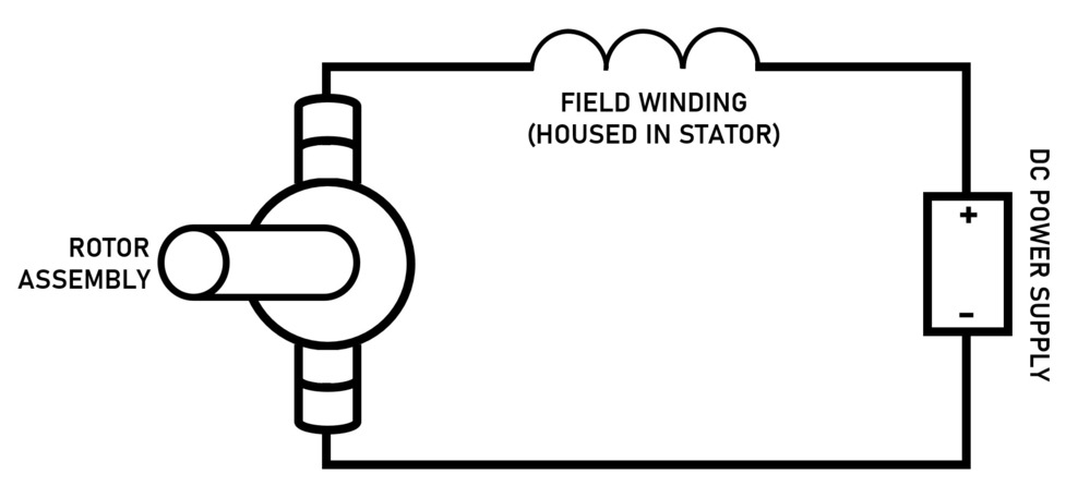
Through examining this diagram, it becomes obvious why these devices are introduced as “series wound” DC motors; their field coil is powered by the DC power source and is wired in a series arrangement with the armature winding. This means the identical current that supplies the armature coils also supports the field windings.
To perform this effectively, the field winding is wound with just a few turns of great gauge wire, so that it can tolerate the full armature current as well as the current of the stator and supply the minimum resistance possible. This is opposite to shunt types, which wire their field coils in parallel configuration with the armature, which generates different effects.
If either the leads of the field coils or the rotor coils are swapped, this can result in the device reversing the rotation direction and makes these devices reversible. Also, with some minor changes, these instruments can operate on AC and are introduced as universal brush motors.
Series Wound DC Motor Specifications
Some basic specifications can help users select the appropriate series DC motor design, and this post will briefly discuss some of them. Note that DC series devices have more features than what is explained in this section, and it only discusses the central values that must be known in most applications.
Rated (Nominal) Voltage
The rated voltage explains the DC power source required to operate the motor. This is the minimum amount to be applied, but a slightly greater value is also possible. Note that employing a larger voltage may result in motor burnout/damage based on the high current in the field coil, so caution must be taken when exceeding the nominal voltage.
Brush Life
These devices use mechanical commutation to use the power supply in the armature coils; therefore, the carbon brushes which are the combining sections for this commutation will finally wear down and should be replaced occasionally. Most DC devices supply the operating life of the brushes in use (commonly in hours) and it is essential to track how long the brushes have been in utilization to prevent damage.
Continuous & Peak Power
The power of a series wound DC motor, expressed in kW or HP, is the output power supplied by the device. A series wound DC motor when in particular applications, must be determined for its continuous power, as the peak value should only be applied for short periods such as in starting cases.
Speed Range
Series wound DC motors, once their output shaft is unloaded, will resume accelerating until they annihilate themselves. This is a consequence of wiring the field coil in series arrangement with the armature and is the most concerning drawback of these devices.
For this reason, these devices should never be operated with no load connected to them, under any situation, and should always be loaded. Most specification sheets present a safe/maximum level of RPMs that will not break these instruments and should be especially considered when selecting a motor model.
Compound DC Motors: Everything You Should Know About DC Compound Motors
Construction of Series DC Motor
The construction aspect of this device is similar to any other form of DC motors in almost all features. It includes all the fundamental parts like the stator housing the field coil or the rotor carrying the armature conductors, and the other essential components such as the commutator or the brush segments all connected in the appropriate sequence as in the case of a generic DC device.
Yet if we take a complete look into the wiring of the armature and field windings of this DC motor, it’s clearly distinguishable from the other forms of this device.
To know that, let us go back to the above discussed basic fact, that this device has a field coil attached in a series configuration to the armature coil. For this reason, comparatively greater current flows across the field coils, and it is designed accordingly as mentioned below.
The field windings of the motor are wound with comparatively smaller turns as the current across the field is its armature current and hence for needed mmf, fewer numbers of them are required.
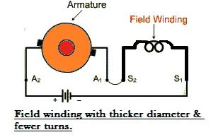
The wire is larger, as the diameter is considerably increased to supply minimum electrical resistance to the flow of complete armature current. Visit here to see the wiring of these motors.
In spite of the above differences about having fewer winding-turns, the running of this DC device remains unaffected, as the current across the field is reasonably large to generate a field strong enough for producing the needed value of torque. To understand that better, we look into the current and voltage equation of a series wound DC motor and it will be mentioned in the following section.
Voltage and Current Equation of Series Wound DC Motor
The electrical schematic of a standard series wound DC motor is illustrated in the diagram below.
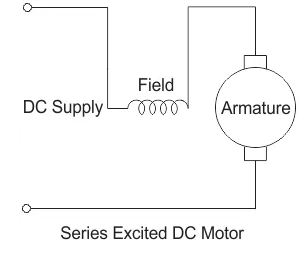
Consider the main voltage and current given to the electrical section of the motor be given by E and Itotal respectively.
Because the entire supply current flows across both the armature and field conductor, therefore:
I_{total}=I_{se}=I_{a}
Where Ise is the series current in the field winding and Ia is the current of the armature. Now from the main voltage equation of the DC motor, we have
E=E_{b}+I_{se}R_{se}+I_{a}R_{a}
Where Eb is the back emf, Rse is the resistance of series winding, and Ra is the armature resistance.
Since Ise is equal to Ia, we can write
E=E_{b}+I_{a}(R_{se}+R_{a})
This is the main voltage formula of a series wound DC motor.
Another significant fact about the DC motor worth noting is that the field flux like in the case of any other DC device is related to field current (Ise is proportional to φ). But since here Ise is equal to Ia and Itotal, so φ is proportional to them.
It means that the field flux is related to the total armature current or the whole supply current. For this reason, the flux generated in this device is heavy enough to create sufficient torque, even with the bare minimum number of turns it has in the field winding.
Speed and Torque of Series Wound DC Motor
A series wound DC motor has a linear connection existing between the amount of torque produced and the field current. It means that the torque is directly related to the current over the total range of the diagram. As in this case, comparatively higher current flows across the heavy series field coil with thicker diameter, the electromagnetic torque generated here is much greater than normal.
This large electromagnetic torque creates motor speed, strong enough to tolerate heavy load overcoming its initial inertia of rest. For this special reason, the motor becomes extremely important as starter motors for most industrial cases dealing in heavy mechanical loads like large metal chunks or huge cranes. Series devices are mostly performed for a very small duration, about only a few seconds, just for the aim of starting. Since if it is operated for too long, the large series current might burn out the series field winding, so leaving the motor useless.
Speed Regulation of Series Wound DC Motor
Unlike the case of a shunt motor, the series wound type has very poor speed adjustment. The series motor cannot maintain its speed on the addition of external power to the main shaft. The main reason is that once a mechanical load is added to the main shaft at any instance, the speed automatically decreases whatever be the form of the device. But the term speed adjustment refers to the capability of the device to bring back the decreased speed to its standard previous amount within a reasonable time. But this device is mainly incapable of doing that as with a reduction in speed (N) on addition of power, the back emf obtained by
E_{b}=\frac{P\varphi ZN}{60A}
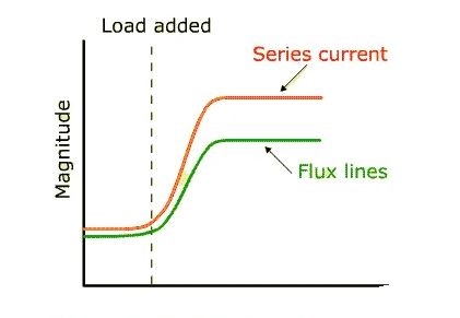
This reduction in back Emf increases the net voltage (E – Eb), and consequently the field current increases, so
I_{se}=E-\frac{E_{b}}{R_{a}+R_{se}}
The amount of series current across the field winding becomes so high that it tends to saturate the field magnetic core. Therefore, the magnetic flux connecting the coils increases at a much slower level compared to the increase in current beyond the saturation rate.
The weak magnetic field generated as a consequence is unable to supply the necessary amount of force to bring back the velocity at its previous amount before application of load.
Applications and Selection Criteria
Because of the large coils found in its windings, these devices present a great deal of starting torque at low speed. They are typically designed to generate the maximum starting torque feasibly and are always employed as starter motors for other devices, or in other industrial cases.
As explained previously, their speed adjustment is quite poor, and speed regulation is just possible through Variable Frequency Drives (VFDs); although, it is mainly not recommended to utilize a series wound DC motor if speed adjustment is important to the design, as other electronic devices have been designed to run this without the added disadvantages, such as induction motors, synchronous motors, and stepper motors (more information can be found in our posts all about induction, synchronous, and stepper motors).
This is not to say that a series wound DC motor is necessarily less beneficial than other electric motor designs. Their non-linear velocity and increased start-up torque have been employed most effectively with great loads, such as winches, cranes, and other devices which must move heavy loads slowly and lighter powers more rapidly. Its variable velocity model allows it to be beneficial for sewing machines, vacuum cleaners, traction applications, power tools, elevators, and much more. It is a workhorse of the new industry and is a great device when used under the correct conditions.
Summary
This post provided an understanding of what a series wound DC motor is and how it works. Therefore, keeping all the above-mentioned facts in mind, a series wound DC motor is most applicable as a start-up motor for industrial cases.



I’m amazed that the word traction only appears once and just before the summary section. Given that a lot of the world’s DC electric railways and tramways employ the series motor this seems to me a major failure in this article. Not all electric railways run on high voltage AC, and two good examples of DC railways that depend on the series motor is the NYC Subway and the London Underground network. I would ask that you reflect this in an edit of this article.
Thanks for visiting our website, Bill! We first apologize for any inconvenience experience you had with this article. Your valuable comment will be considered for the next update of the post.