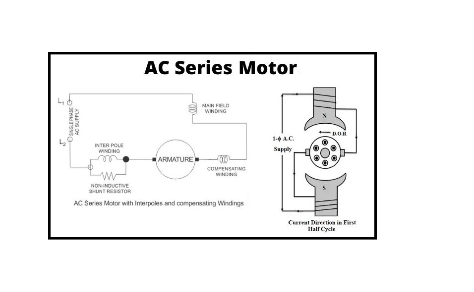
What is AC Series Motor? A series motor can be operated based on either DC or AC (single-phase) source supplied that both rotor and stator cores are laminated to restrict the iron wastes. The cross-sectional view of an AC Series Motor attached to an AC supply is typically used to define these motors. As the armature current changes, the field polarity varies in phase with it; consequently, the torque produced is unidirectional with a pulsating part over and above the mean value.
A commutator-type motor known as the AC Series Motor may operate on either a single phase of dc power or ac power. A conventional dc series motor will produce a unidirectional torque and revolve as a result if it is linked to an ac supply because of the simultaneous reversal of field and armature currents. AC series motors are available from a variety of suppliers and companies, as well as various Manufacturers and distributors, and there are several AC Series Motors For Sale on Linquip. Please contact AC Series Motor Experts in Linquip to learn more about how to connect with a diverse group of service providers who consistently deliver high-quality products.
What is an AC Series Motor?
The AC series motor is also introduced as the modified DC series motor as its structure is very similar to that of the DC type. Before explaining these variations, it is important to discuss the requirement and where we require to perform modifications. In order to know this, consider this main question. What will occur when we give an AC source to a DC series motor? The answer to this question is explained below:
- An AC source will generate a unidirectional torque since the direction of both the currents (i.e. field current and armature current) reverse at the same time.
- Due to the alternating current, eddy currents are produced in the field and yoke cores which causes excessive heating of the field and yoke cores.
- Because of the high inductance of the armature and the field circuits, the power coefficient would become very low.
- There is some sparking at the DC device brushes.
So, considering the above tips, we can explain that we don’t have an appropriate operation of a DC series motor on our application with an AC source. Now in order to decrease the eddy currents, there is the requirement to laminate the field and yoke cores. This is our first variation in the DC series motor.
About the power coefficient and its improvement, we know that the power coefficient is directly proportional to the reactance of the armature and field circuits, and we can decrease the field winding reactance by minimizing the number of turns in the field core.
But there is one drawback: on decreasing the number of turns, the field mmf will reduce and because of this, the air gap flux will drop. The main result of this is that there is an improvement in the speed of the device but a reduction in the device torque, which is not suitable. Now how to overcome this disadvantage? The best method is the use of a compensating coil. On the foundation of the usage of compensating coil, we have two kinds of the motor including:
- Conductively compensated type of motors
- Inductively compensated type of motors
Conductively Compensated Type of Motors
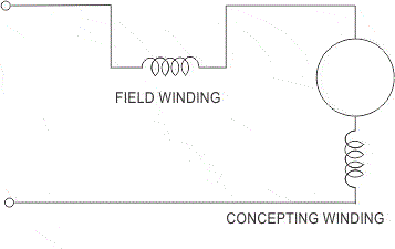
The circuit diagram of the conductively compensated type of motors is presented below. In this form of motors, the compensating coil is configured in a series arrangement with the armature circuit. The coil is set in the stator slots. The axis of the compensating coil is 90o (electrically) with the basic field axis.
Inductively Compensated Type of Motors
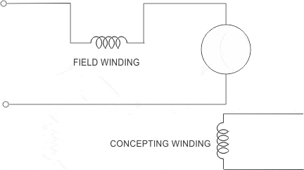
The circuit diagram of the inductively compensated type is shown below. In this kind of device, the compensating coil has no interconnection with the armature section of the system. In this form, a transformer operation will take place as the armature coil will perform as the primary winding of the transformer and the compensation coil operates as the secondary winding. The current in the compensating coil will be in the opposed phase to the current in the armature coil.
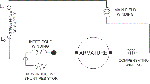
The complete schematic system of the single-phase AC series motor with all the variations (i.e. compensating coil and inter pole) is presented below.
Speed regulation of this form of the motor is best achieved by solid-state instruments. The device has numerous applications such as hair dryers, portable drills, kitchen appliances, table fans, etc. We have already explained the advantage of having a compensating coil. Let us present what the use of the inter pole is. The main operation of the inter poles is to enhance the operation of the AC series motor in terms of better efficiency and higher output from the given size of the armature section.
We have taken very great reactive voltage reduction of the series field as compared to either the compensating field or the armature to decrease the series field inductance. The coil of the inter pole circuit is arranged in a parallel form with the non-inductive shunt as presented in the above figure.
Working Principle of the AC Series Motor
The working principle of the AC series motor is identical to the DC type. When the AC series motor is attached to the AC source, the alternating current begins flowing across the armature and field coils.
The field coil generates an alternating flux (φ) that performs with current flowing in the armature coil to create torque. Since both field and armature currents reverse simultaneously, the torque often is made in the same direction.
Because of its great starting torque and high speed, it can be used in more applications. If you want to know more about an AC series motor, visit here.
Motor particularly modeled to operate on DC power suffers the following disadvantages once it starts on the single-phase AC source:
- Its efficiency is low because of the hysteresis and eddy current wastes.
- Its Power coefficient is low because of the large reactance of armature and field coils.
- Sparking at the brushes is more.
To set efficiently on the AC source, the following constructional modifications are required to perform:
- The field winding is manufactured by applying a material that has low hysteresis wastes and is laminated to decrease eddy current.
- The field coil is made with a few numbers of turns. So, the pole area increases and the flux density reduces. This process reduces the iron wastes and reactive voltage.
- The number of armature conductors increases to obtain the necessary torque with a low flux. A compensation coil is employed to decrease the armature reaction and increase the commutation.
Principle of Operation of AC Series Motor
A typical DC series motor will operate in an identical direction regardless of the polarity of the source. The direction of the torque is based on the relative directions in the gap of flux and armature current. If the terminals of the line are reversed, both the armature and field currents are reversed, the direction of torque remains constant. Thus, the device continues to slide in the same direction.
So once the standard DC series motor is attached to an AC source, both armature and field currents reverse simultaneously and the unidirectional torque is generated in the device.
If the alternating current is in the positive half of a two-pole motor, the polarity of the field poles and the currents flowing across the armature conductors will be as shown in Figure below. Under N-pole, the armature conductors carry inward currents of +ve, and under S-pole, outward currents of -ve. The torque produced in the armature will try to rotate in an anti-clockwise direction, according to Fleming’s left-hand law.
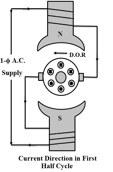
During the next case, the alternating current goes across the negative half cycle of the section. Now the current across the armature and the field winding will also vary. It will be again obvious that the armature will try to move in the same direction due to the uniform torque produced by the two halves of the system.
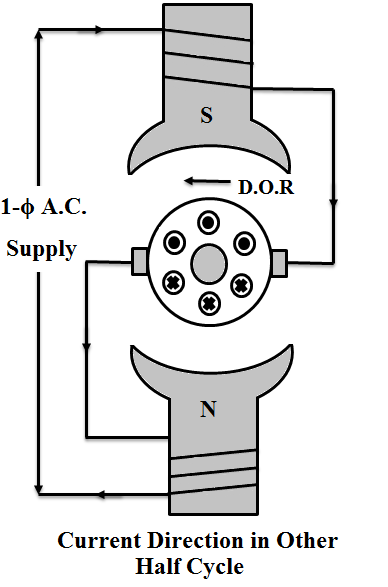
Thus, the series motor can perform on both the DC and AC supplies. The operation of a DC Series motor is based on the AC source is not satisfactory because of the following reasons:
- The efficiency is not suitable. This is due to the increase in core wastes because of the alternating flux.
- The reactance of the armature and field windings rises as the source given is alternating, which makes the device operate at a low power factor.
- Significant sparking at brushes will happen. This is because of the poor commutation. The voltage produced by the transformer performance in the coil undergoing commutation further intensifies commutation problems.
Constructional Features of the AC Series Motor
Constructional features and modification tips in the design of an AC series motor are:
- Some changes are needed to have a satisfactory function of the DC series motor on the AC source when it is called an AC series motor.
- Fully laminated yokes and poles should be applied in order to decrease eddy current wastes.
- The power coefficient can be raised by reducing the armature and field reactance.
- In order to decrease the field reactance, the field coil is modeled with a fewer number of turns. Lower pole flux also decreases the transformer EMF in the commutating winding.
- The motor must be supplied with a large number of poles each providing less flux per pole.
- A reduction in the number of turns on the field coil would also decrease the field flux. To keep the torque fixed and smooth on the shaft, the armature turns must be increased relatively. This can increase the armature reactance and its reaction.
- Compensating coil should be used to drop the armature reactance as far as feasible. Compensation also enhances the commutation.
- The flux generated by the compensating coil is opposite to that created by the armature and effectively offsets the armature reaction.
- The armature windings are single-turn brushes and coils of less width are employed to prevent the short circuit condition.
- The air space is designed very small so that smaller field turns can be applied per pole.
- The frequency of the source is reduced. Therefore, since the transformer EMF is related to frequency, an appropriate commutation is possible at lower frequencies.
Characteristic of the AC Series Motor
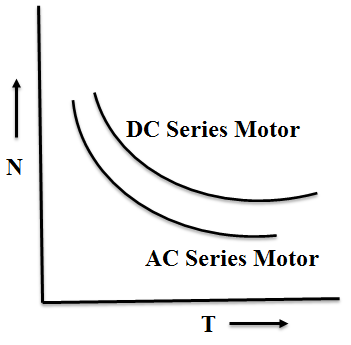
The characteristics of the AC series motor are identical to that of DC types. The torque is related to the square of the armature current (TI2) and the velocity is inversely related to the armature current. The series motors should often be started with some load on them since the start-up speed of the device is very great because of the high starting torque.
Application of the AC Series Motor
- Sewing machines
- High-speed vacuum cleaner
- Electric shavers
- Used in drills and power tools
Download AC Series Motor PDF
Read More on Linquip
- What is AC Motor? Types, Principles and Constructions
- Everything You Need to Know About Working Principle of AC Motor
- Working Principle of AC Motor: 2022 Ultimate Guide
- What is a Series Wound DC Motor?
- Series DC Motors: A Comprehensive Guide
- 10 Types of CNC Machine + Applications & PDF
- 13 Parts of CNC Machine + Function & PDF: A Clear Guide
- What Is CNC Machining & How Does It Work? (A Comprehensive Guide)
- Working Principle Of DC Motor: 2022 Complete Guide
- Working Principle of Stepper Motor: 2022 Ultimate Guide
- Working Principle of Induction Motor: 2022 Full Guide
- Efficiency of Induction Motor: Calculation & Equation
- What is Gear Shaft? Clear Principle & Advantages

