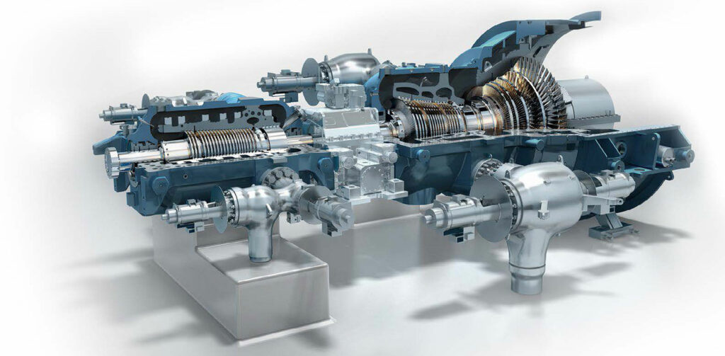
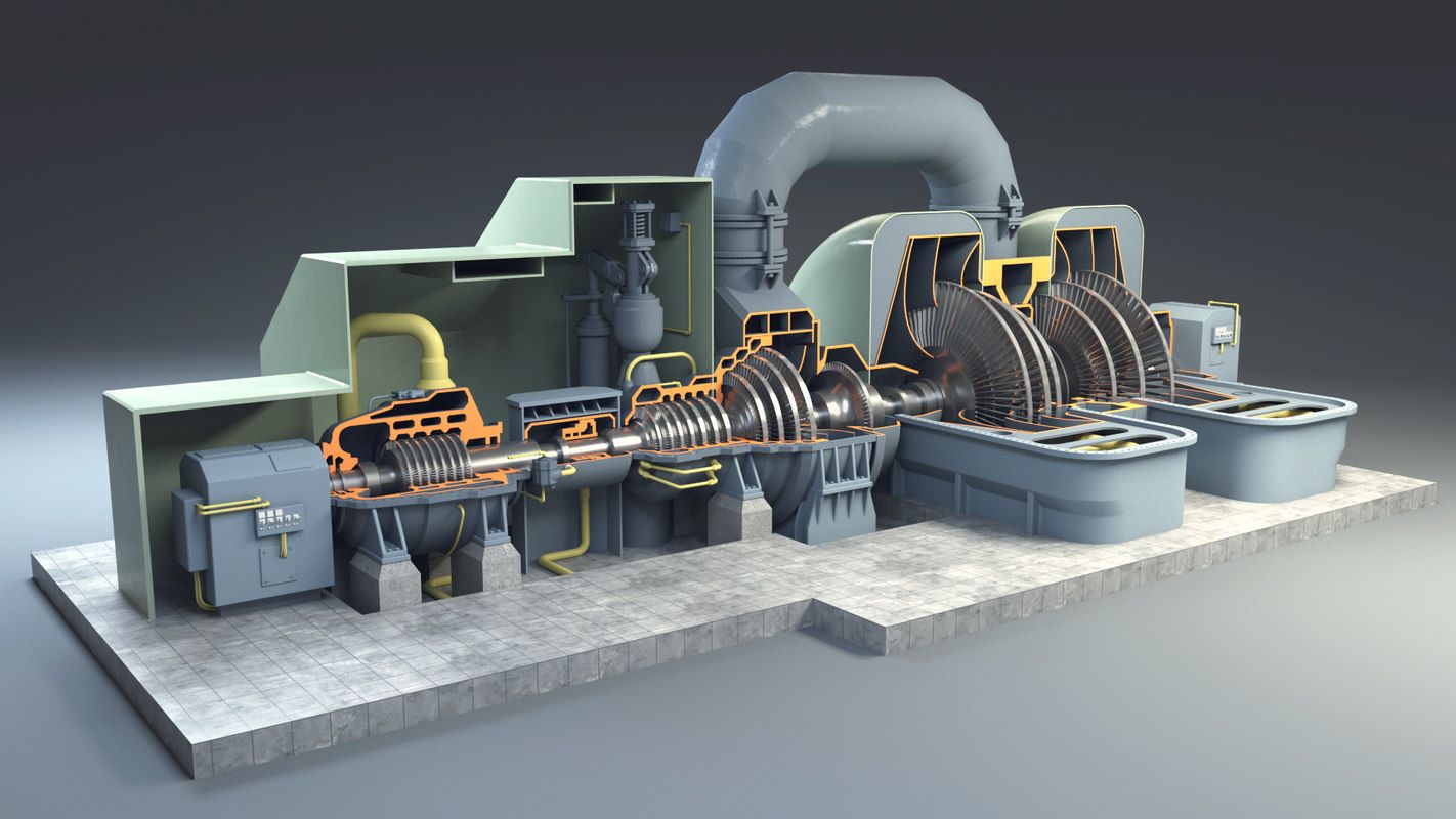
Welcome to Linquip Blog. Today we are going to have a look at the Steam Turbine parts. All steam turbines are made up of the same components, but depending on the type of turbine, these components come together in different ways. We also try to introduce you to these components and make you more familiar with the construction of steam turbines.
Our team has gathered all of the necessary information on this topic to eliminate the need for reading diverse content on other websites. Stay with us until the end to find the answer to your question on this topic. We have a long journey ahead of us, so take a deep breath, sit back, and keep reading this article until the end.
Parts of a Steam Turbine
All steam turbines have the same basic parts, though there’s a lot of variation in how they’re arranged. The components of each steam turbine are classified into 10 categories. Each of these components has a unique function, and along with the other components causes the final operation and the ultimate goal of the steam turbine, which is the production of power and kinetic energy.
In the following, you will read about each of these components and we will explain the role of each in steam turbines.
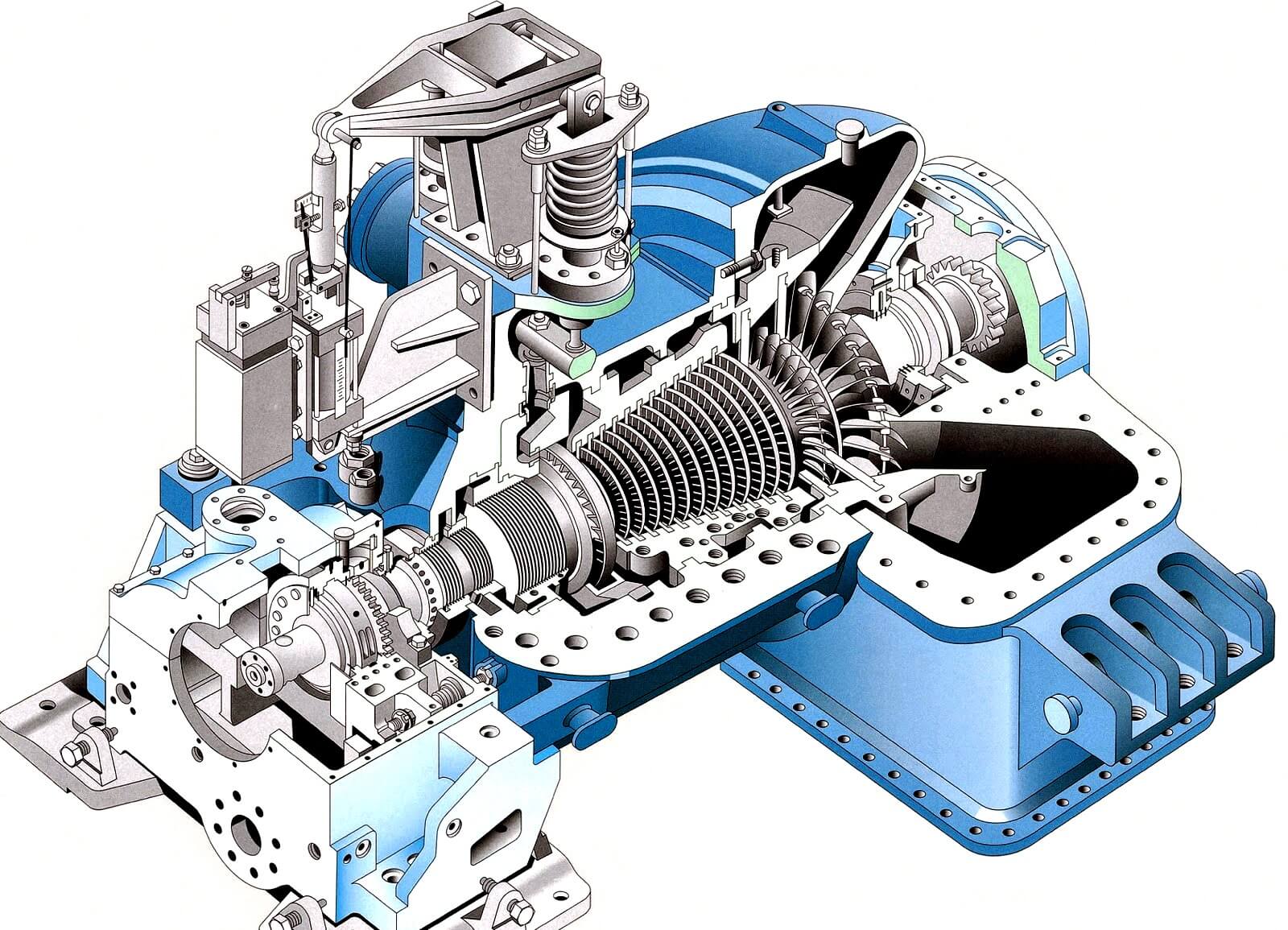
- Steam chest and the casing: This part is connected to the higher pressure steam supply line and the low-pressure steam exhaust line respectively. The steam chest connected to the casing houses the governor valve and the over speed trip valve. The casing contains the rotor and nozzles through which the steam is expanded and directed against the rotating buckets
- Rotor: The rotor Consists of shaft and disk assemblies with buckets. The shaft extends beyond the casing through the bearing cases. One end of the shaft is used for coupling to the driven pump and the other end of the shaft serves the speed governor and the over speed trip system.
- The bearing cases: as mentioned in the rotor part, the bearing cases are connected to the rotor and support the rotor and assemble casing and steam chest. The bearing cases contain the journal bearings and the rotating oil seals, which prevent outward oil leakage and the entrance of water, dust, and steam. The steam end bearing case contains the rotor positioning bearing and the rotating components of the over speed trip system. An extension of the steam end bearing housing encloses the rotating components of the speed.
- Casing sealing glands: Seal the casing and the shaft. Spring-backed segmental carbon rings used for this and supplemented by a spring-backed labyrinth section for higher exhaust-steam.
- Governor system: Governor systems are speed-sensitive control systems that are integral with the steam turbine. The turbine speed is controlled by varying the steam flow through the turbine by positioning the governor valve. Consists of spring-opposed rotating weights, a steam valve, and an interconnecting linkage or servo motor system. The governor sense turbine shaft speed through direct connection, worm/worm wheel, or magnetic impulse from a gear. The turbine speed is compared to some predetermined set point and the governor output signal to a servo motor. Change in the turbine inlet and exhaust-steam conditions, and the power required by the pump will cause the turbine speed to change. The change in speed results in repositioning the governor weights and subsequent repositioning of the governor valve.
- Labyrinth seal: Labyrinth is a means of reducing leakage from high pressure side to low pressure side by allowing a small amount of leakage. The clearance between labyrinth and shaft is kept at the minimum possible.
- Nozzle ring and reversing blade assembly: The nozzle ring is bolted to the inside bottom half of the steam end casing. The nozzles located in the nozzle ring, direct the steam flow from the steam chest to the Curtis stage first row blades. The reversing blade assembly is located between the blade rows of the Curtis stage (the Curtis stage has two rows of blades) and is bolted to the nozzle ring. The reversing blades reverse the steam flow as it exits the first row of blades and directs the steam into the second row of blades of the Curtis stage. The reversing blade assembly is positioned axially by spacers.
- Sentinel valve: This is a warning device located on the top of the exhaust end turbine casing, indicates excessive turbine exhaust end casing pressure. In the event the casing pressure exceeds a predetermined setting above the normal operating pressure, the valve releases a small amount of visible steam to the atmosphere, causing an audible sound. This valve will not serve as a relief valve.
- Auxiliary steam valves: Auxiliary valves are used to achieve more efficient operation with varying load or steam conditions. The valves are provided in the steam passageway (in the bottom half of the steam end turbine casing) between the steam chest and nozzle ring. The passage is cast in three separate compartments.
One compartment is continuously open for steam flow to a bank of nozzles in the nozzle ring. The other two are fitted with auxiliary hand valves to control the flow of steam to two other banks of nozzles in the same nozzle ring. - Turning Gears: Large turbines are equipped with turning gears to rotate the rotors slowly during warm-up, cool off. This is to maintain the shaft or rotor at an approximately uniform temperature circumferentially, so as to maintain straightness and preserve the balance.Read More on LinquipTypes of Steam Turbine: An easy-to-understand and practical ClassificationSteam Turbine Efficiency: Complete Explanation
- Carbon Ring Seals: It consists of carbon ring segments and these segments held together by retaining spring. Anti-rotation stops fit in the notches in the bottom half interstage diagrams (casing) and carbon rings prevents the rotation.
- Diaphragms: Stationary diaphragms separate the inner stages, contain the interstage nozzles and interstage seals. The nozzle expands the steam and direct it against the following rows of rotating blades. The diaphragms are adjusted on assembly to allow for rotor deflection and to assure that the seals are concentric with the shaft.
The bottom half of diaphragms are located vertically in the casing grooves by shims at the bottom of the grooves and laterally by means of adjusting screws at the horizontal joint. The top halves of the diaphragms are fixed in the casing by the same arrangement and lift with the casing cover. - Over-speed trip system: The trip mechanism acts independently of the governor-controlled system and closes the trip valve to stop the flow of steam to the turbine in the event of an over-speed condition. Consists of a spring-loaded pin or weight mounted in the turbine shaft on a collar, a quick-closing valve that is separate from the governor valve, and interconnecting linkage. The centrifugal force created by the rotation of the pin in the turbine shaft exceeds the spring loading at a preset speed.
- Turbine Cylinders: Turbine cylinders have to withstand the pressure of the steam and for this reason, they are of robust design with thick walls. They are also subject to high steam temperatures which, for thick-walled components, are not desirable. Temperature gradients within rigid components set up high stresses in the material which, when coupled with mechanical stress due to pressure, can cause the failure of the material.
Furthermore, the overall expansion of the components must be accommodated. Also, during heating and cooling the temperature gradients become particularly adverse as larger parts take longer to change their temperature than smaller parts. To withstand pressure, thick cylinder walls are required but, to minimize thermal stress, there should not be abrupt changes in thickness nor asymmetrical arrangements. This leads inevitably to smooth rounded profiles of the stress-bearing components. Also
uniform heating of components is desirable so as to avoid differential expansion and undue thermal stress.
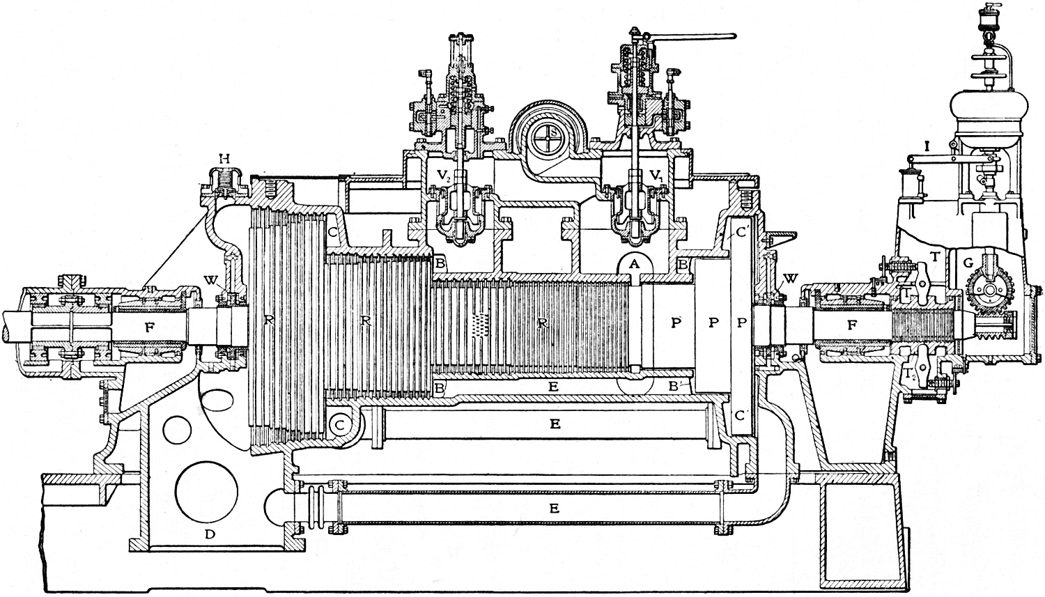
This requires sections of uniform thickness and provision for circulation of steam within the casing as shown in Figure 1 to promote uniform temperature changes, particularly during startup of the unit. Steam access into and out of the cylinder must also be accommodated and this requires special nozzles and reinforcing of the casing in these areas. The incoming stream is at a temperature higher than that generally prevailing in the cylinder necessitating appropriate arrangements to take account of thermal stress and differential expansion in these areas.
In order to assemble the turbine and disassemble it for maintenance, the casing must be split in some way. The joint is normally horizontal so that the upper half can be removed leaving the lower half in position with the rotating parts. This joint must withstand the pressure in the casing and the flanges are particularly thick and robust. These flanges may be subject to distortion during the heating and cooling of the casing.
Conclusion
The present article was an attempt to deliver all the essential information about the steam turbine parts. Steam turbines are the most important machines in the energy conversion field. Knowing the components of the steam turbine, in addition to increasing your technical knowledge of this machine, will make you more familiar with the overall construction of the steam turbines and have a clear understanding of how it works.
If you have any experience or encounter with steam turbines and know more about their parts, we will be very glad to have your opinions in the comments on our website Linquip. Moreover, if you have any questions about this topic, you can sign up on our website and wait for our experts to answer your questions. Hope you enjoyed reading this article.


If we are going to procure installed old Steam Turbine, then what are parts need to check for condition of machine and in view of operational parameters , what are those parameters need to check,
Thanks for visiting our website. You can solve your issue by asking from one of our experts here.