A Thermistor is a Thermal Detection Resistor of Temperature Transducers that presents a foreseeable and precise variation in resistance based on temperature changes. Its distinctive composition is the main aspect of how much its resistance will modify. Generally, thermistors are part of a greater group, including passive components. These passive instruments are not equipped to supply power gain or amplify a circuit, unlike their active component counterparts.
What is a Thermistor?
Thermistors are a kind of semiconductor, while they have a higher resistance than conducting materials, but their resistance is lower than insulating substances. A thermistor is a resistance thermometer or an instrument such as a resistor whose resistance is based on temperature. The term is a composition of “resistor” and “thermal”. It is made from metallic oxides, compressed into a bead, disk, or other cylindrical systems, and then enveloped with an impermeable substance like glass or epoxy.
Michael Faraday, an English researcher, first presented the idea of them in the 19th century while working on the silver sulfide behavior. He observed that the resistance of silver sulfides reduced when the temperature increased. This concept would finally result in the construction of commercial ones in the 20th century when Samuel Ruben made the first of them.
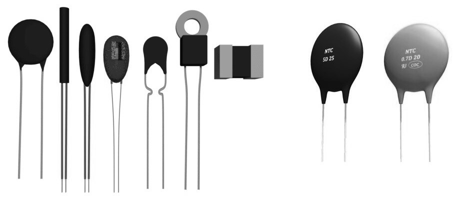
The dependence between a thermistor’s temperature and its resistance is extremely based on the substances from which it’s contained. The producer usually specifies this characteristic with a high degree of accuracy, as this is the main feature of interest to their users.
Thermistors are made of binders, stabilizers, and metallic oxides, compressed into wafers and then slice to chip size, left in a disc shape, or produced into another shape. The exact proportion of the composite substances control their resistance-temperature graph. Producers must control this ratio to determine how the Thermistor will operate. Visit here to see the construction process of them clearly.
Types of Thermistors
There are different classifications for thermistors based on various characteristics and definitions. The first is based on the way they respond to heat. Some raise their resistance with increasing temperature, while others represent a drop in resistance. These two main types are PTC or Positive Temperature Coefficient , and NTC or Negative Temperature Coefficient. The fundamental difference is that NTCs demonstrate a DECREASE in resistance when the temperature increases; otherwise, PTCs present an INCREASE in resistance in the same condition.
The relationship between temperature and resistance is non-linear, but a linear correlation can be presumed over a few modifications. In this type, a first-order temperature coefficient of resistance can be introduced as a “k” factor. The value of k is positive for some thermistors, while for others, it is negative. As a result, it is feasible to classify thermistors according to this aspect of their procedure.
- Negative temperature coefficient (NTC thermistor): This kind has a feature where the resistance reduces with increasing the temperature, i.e., k is negative. The term NTC thermistor is normally utilized in component data and datasheets.
- Positive temperature coefficient (PTC thermistor): The value of k is positive in this kind, which means that the resistance increases with increasing temperature.
NTCs and PTCs Application
Some applications for NTC and PTC Thermistors are mentioned below:
- Measurement of temperature
- Temperature Compensation of temperature in buildings
- Temperature Control and monitoring temperature
- Inrush Current range limiting in Inrush models
Advantages of NTC and PTC Thermistors
These types of thermistors have some important benefits in practical operations, including:
- NTC and PTC are powerful, stable, and dependable. Therefore, they are used to control harsh environmental situations and noise more than other types.
- They have a compact size, which allows them to work in small spaces. They also take up little real estate on circuit boards. This small dimension permits them for a fast response time due to variation in temperature, which is vital when quick feedback is needed.
- These thermistors are less expensive than other kinds of temperature sensors; if the Thermistor has the right RT curve (Resistance-Temperature), no other calibration is required during its installation.
- They can achieve a particular resistance precisely at a particular temperature based on their curve match.
Thermistor Types Based on Material
In addition to the character of the resistance modification, they can also be classified according to the type of material utilized.
Precision Interchangeable Thermistors
Some manufactures construct high precision devices based on the specific resistance-temperature curve. These instruments provide a broad temperature range interchangeability and remove the requirements to calibrate individually or supply compensation for circuit variability.
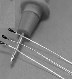
They provide accurate temperature measurement to ±0.2°C between 0 to 70°C. Click here to explore more about the performance of this type.
Selection Considerations of Precision Interchangeable Thermistors
Choosing the appropriate type of them has some important considerations:
- Providing the Power Dissipation
- Determining the Temperature Coefficient and Resistance Value
- Constant of Thermal Time
- Range of Temperature
Precision Interchangeable Thermistors Applications
There are various methods for measuring temperature electronically. Developments in technologies are used in temperature measurement systems, which are too economically. A/D converters, interface electronics, microprocessors, and displayers are common and available applications of them.
This model of thermistors is utilized in applications that need a high level of accuracy in a wide temperature range. By changing the equation of the resistance and temperature, it can be employed for various temperature intervals.
These thermistors can supply a 1 mW/°C range. Therefore, some particular errors are possible by additional current flow in some circuits. Manufacturers recommend that circuits should be designed to select the highest resistance value to prevent this type of error.
Glass Encapsulated Thermistors
Glass Encapsulated thermistors are a particular branch of NTC thermistors. These microscopic thermistors are fully sealed and eliminate resistance reading errors. These errors are usually caused by humidity. So, they operate effectively in severe environmental situations.

This kind of thermistors has no limitations, which enable them to provide a wide operating range between -55 to +200 °C. Their small size allows them to be used in a variety of housings like hex nuts and ring lugs. They also provide long-term durability and quality for precise temperature sensing applications. They are commonly used in industries such as HVAC, Medical, and Automotive.
Features of Glass Encapsulated Thermistors
- Sensitive resistance and wide operating range of temperature between -40 to 250 °C.
- A fast response makes them an effective alternative to thermocouples and RTD probes.
Applications of Glass Encapsulated Thermistors
- Monitoring and measurement of the Temperature in HVAC applications.
- Temperature control in usual household appliances like refrigerators and ovens.
- Industrial applications like battery pack terminals in a charge condition.
- Medical applications that depend on airflow like respirators.
- Infrared lighting systems in outdoor applications.
PAN Thermistor Temperature Sensing Probes
This type of sensing probe is produced from a particular-formulated metal oxide ceramic substance that is extremely accurate in temperature detecting. These NTC thermistors are simple to combine all form factors. They have extremely fast response time and high accuracy, which can be determined up to ±0.2ºC.
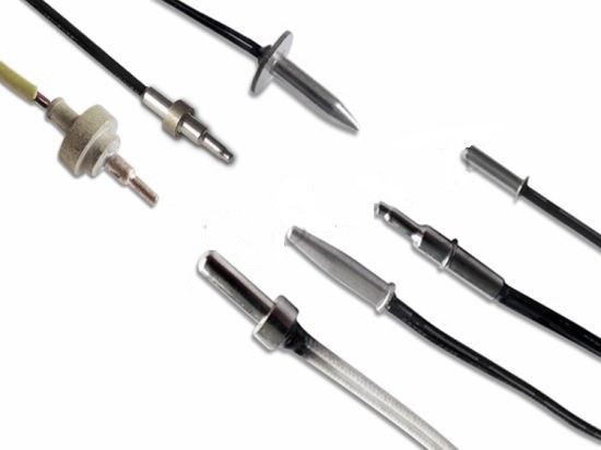
PAN Thermistor Temperature Sensor Characteristics
PAN thermistor electrical features are presented to describe the resistance and temperature range of the Thermistor. Understanding them is necessary to choose the best Thermistor for a particular application. All PAN series have the following features:
- Nominal Resistance at 25°C
It presents the reference needed for the calculation of the resistance at any other condition and permits the selection of the perfect sensor for a particular application.
- Temperature Coefficient of Resistance
It determines the sensitivity of the resistance based on temperature response and is introduced as %/°C.
- Resistance Tolerance (5%, 3%, 2%, 1%)
It can be found by multiplying the specific temperatures.
- Temperature Tolerance (1.0°C, 0.5°C, 0.2°C, 0.1°C)
It presents a deviation in temperature from the common R-T diagram of a thermistor. The tolerance of temperature is consistent across a particular temperature range. Resistance Tolerance is normally determined for these thermistors.
- Thermal Time Constant (Secs)
It determines the necessary duration for the Thermistor to modify a particular difference between the initial temperature and the final one.
- Temperature Accuracy (ºC)
It can be evaluated as resistance tolerance related to the temperature coefficient.
- Maximum Power Rating (mW)
The Thermistor will operate for a particular period while providing the acceptable stability of its properties.
- Dissipation Constant (mW/°C)
It determines the ratio of variation in the Thermistor’s power to the modification in body temperature at a particular temperature.
- Material Constant (°K)
It presents the diagram of the R-T and is a detector of resistance at a specific temperature compared to resistance at another one. It also needs two R-T data sets and is extremely accurate for most industrial applications. It is usually calculated between 25 to 85°C temperature range.
Disc and Chip Style Thermistors
DISC and CHIP style thermistors have a resistance ranging from 1.0 to 500,000 ohms. These instruments are desirable for a wide range of resistance values and temperature coefficients. Their standard resistance tolerances are from 5 to 20%. All of them are determined at 25°C.
Thermistor Terminology for Disc and Chip Style Thermistors
The most important constant is the particular ratio, usually presented in milliwatts per degree (mw/°C), at a particular temperature, of a change in power dissipated in a thermistor to the resultant change in body temperature.
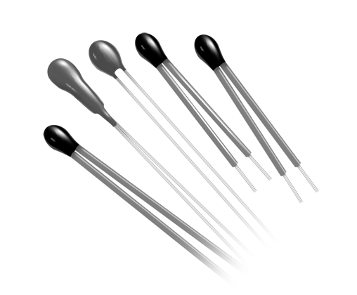
Another important constant is the thermal time constant, which is necessary for a thermistor when subjected to a specific function modification in temperature and is usually presented in seconds (S).
Selection Considerations for DISC & CHIP Devices
The power supply is a usual problem in the thermistors as they can only provide a certain range of power. Most thermistors normally operate from 1 to 25 mW/°C. This means that the resistance modifies 1°C for each range “mW/°C” for the chosen instrument.
Temperature error that happened by self-heating must be less than the needed detector accuracy to obtain a high level of accuracy for many applications. Various options are available to increase the thermistor resistance and decrease the thermistor power, like reducing the source voltage and/or raising the series form resistors in the main circuit.
For instance, if the constant of the selected Thermistor is 5 mW/°C and the power provided by it is 20 mW/°C, a 4°C error happens according to the self-heating effect. To reduce this effect, a factor can be extracted easily by taking the rating time coefficient about 10 to 1 and using it in the power circuit to generate a perfect value of the maximum available power. It can compensate for the self-heating error and provides the maximum power effectively for the device.
Inrush PTC Thermistor
Some manufacturers introduce a new PTC thermistor, which has the circuit protection feature and provides a high-voltage industry rating of about 680 (V).
Key Features of Inrush Thermistors
- Providing great current about 20 (A) at peak voltage condition
- Normal Resistance at 25 °C is 50 (Ω) with a tolerance of about 20%
- Suitable dissipation coefficient of 55.0 mW/°C
- Their Heat capacity is near 5.45 J/°C
- The Thermal time constant is about 62 (s)
- Their Radial-leaded cover for simple PCB mounting
Target Applications of Inrush Thermistors
Inrush thermistors are used in applications including current limiting such as welding devices and plasma cutter instruments with exceedingly high voltages between 480 to 930 V. They can tolerate maximum inrush currents without deformation with this high voltage level.
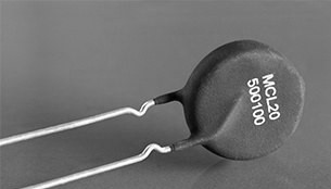
The device provides a short reset time, so a fast reset will not result in a huge inrush current like a PTC thermistor because its resistance is already in high condition. As a result, they are extremely reliable in high-voltage applications. These thermistors present a cost-effective alternative for combining a power resistor or relay on systems to operate with similar functionality.
Working Principle of a Thermistor
A thermistor does not practically “read” anything; instead, the resistance of a thermistor modifies with temperature. The amount of the resistance variation is based on the kind of material utilized in the Thermistor.
Unlike other sensors, thermistors are typically nonlinear, meaning the points on a graph demonstrating the relevance between temperature and resistance will not create a straight line. The position of the line and how much it varies is specified by the production of the Thermistor.
Using a Thermistor to Detect Temperature
So how can we employ a thermistor to detect the temperature? As discussed before, we understand that a thermistor is a resistive instrument, and therefore according to Ohms law, a voltage reduction will be generated across it by passing a current. A thermistor is a passive kind of a sensor, so it needs an excitation alarm for its function.
The easiest way of applying this is to employ the Thermistor as a section of a potential circuit. A constant voltage is applied through the resistor to supply this. For instance, we use a 5kΩ thermistor with another 5kΩ series resistor. Therefore, the external voltage at the 25oC will be half the supply voltage as 5Ω/(5Ω+5Ω) = 0.5.
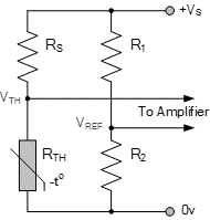
The resistance of the Thermistor varies according to the changes in temperature, so the value of the supply voltage within the Thermistor will also be modified, generating an output voltage which is based on the total series resistance in the terminals. Therefore, the practical circuit operates as a simple resistance to voltage converter. The resistance of the Thermistor is detected by temperature. So, the hotter the transducer, the lower the voltage.
If the designers reverse the position of the series resistor, the output voltage will modify in the opposite direction. In this form, the hotter the Thermistor, the higher the voltage.
Thermistor Structure & Composition
Thermistors have a lot of sizes and shapes, and they are manufactured from a variety of substances based on their considered application and the temperature range they require to work. According to their physical shape, they can be made as flat discs for applications where they require to be in touch with a flat plane. Nevertheless, they can also be constructed in the form of rods for utilization in temperature applications. Actually, the practical form of a thermistor is based on the needs of a specific application.
Metallic oxide thermistors are usually utilized for temperatures between 300 to 700 K. These thermistors are constructed from a tiny powder substance that is sintered and pressed at high temperatures. The most usual materials to be utilized for these thermistors are Nickel oxide, Cobalt oxide, Copper oxide, Manganese oxide, and ferric oxide.
Semiconductor thermistors are employed for extremely lower temperatures. Germanium thermistors are greater utilized than their silicon samples and are employed for temperatures below 100 K. Silicon thermistors can be utilized at temperatures up to 250 K. The Thermistor itself is constructed from an exclusive crystal that has been made in a specific level of chemical materials.
Thermistors Production Cost
How much will it cost for their production? The production cost of Thermistor is based on a series of matters, such as technology, quality, raw substance, etc. If we want higher standard construction, we should often pay higher prices. It’s a key matter influencing the profit and earnings.
If the designers pay attention to it, they might consider the profit. When the designers focus on this, it’s feasible that they try to reduce it. A whole supply process is obviously helping producers to reduce the costs. Today, this is really a tendency in the business due to the M&A subject.
Raw Material Blend
Thermistor designers start with the exact blending of raw materials into a perfect organic method. These raw substances are coated with metal oxides like nickel, cobalt, manganese, and copper oxides. Other stabilizers are also added to the mixture. The binders and oxides are combined, employing a new technique introduced as ball milling. The substances are blended during this process, and the particle size of the oxide covers is decreased. The composition of the different metal oxides specifies the resistance-temperature properties and the ceramic component resistivity.
Resistance Test
All thermistors are evaluated for appropriate resistance value, usually at 25°C. The chips are automatically examined, but they may also be tested manually based on quality, quantity, and performance. The automatic chip controllers are faced with resistance tests of instruments and particular computers, which are programmed to locate the chips in several bins based on their resistance range.
All automatic chip controllers can evaluate approximately 9,000 devices per hour with high accuracy. In addition, a particular little fuse has too many controllers that can identify the finished thermistors. These automatic sorters increase the quality of the product and reduce the production time and costs.
Termination
Thermistors are usually supplied with particular terminals joined with lead wires. These terminals are used in special application machines. They may be inserted into metal or plastic housings before delivering to the customer.
Probe Assembly
Thermistors are often combined with probe housings for environmental considerations or for mechanical protection. These housing can be constructed from materials including vinyl, brass, stainless steel, epoxy, plastic, and aluminum. They not only provide a desirable mechanical attachment for the thermistor element but also can protect it from the environmental effects. The appropriate option of lead wire, insulation lead wire material, and coating material will supply a fully-sealed section between the Thermistor and the surrounding.
Marking
The perfect Thermistor can be marked for simple recognition. This can be done using a color dot, a date code, or a part number. The coating substance on a thermistor body may have added color in certain applications in order to be specified. A color dot is normally added to the thermistor body applying a dip-coating procedure. Marking that needs numeric or alphabet characters is done with a specific marking device. This device easily signs the instrument with stable ink. The ink is made at a high temperature.
Final Inspection
All completed products are evaluated for electrical and physical faults depending upon the “Zero Defect basis”. All parameters must be documented before the sales of any product.
Buy Equipment or Ask for a Service
By using Linquip RFQ Service, you can expect to receive quotations from various suppliers across multiple industries and regions.
Click Here to Request a Quotation From Suppliers and Service Providers
Read More on Linquip
- What is the core difference between Thermistor and RTD?
- Types of Thermistor; A Fundamental Comparison Between Them
- Difference Between Thermistor and Thermostat: which one outperforms the other?
- Thermistor Resistance: How does it Calculate?
- Thermistor vs. Thermocouple: Complete Comparison & Practical Selection Guide
- What are the Different Types of Actuators?
- The Only Guide You’ll Ever Need For Different Type of Industrial Measuring Tools
- What is PTC Thermistor? (Applications & Advantages)
- What is NTC Thermistor? (Types, Applications & Advantages)



Amazing
Thank you for your comment.