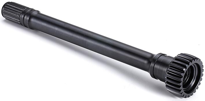
What is Gear Shaft? A gear shaft is an essential part of the overall transmission that bears the shear stress and torsion. The transmission, or gearbox, is a system that can be applied to monitor the application of energy by reducing or increasing speed, increasing torque, reversing rotation, or varying the driveshaft direction. All gearboxes have an output side and an input side. The output shaft carries the energy from the input shaft and operates at different speeds, according to the gears and gear ratio. The input shaft is attached directly to the motor and controls the motor speed. It brings the controller into the gearbox network and tolerates the torque produced by engaged gears.
What is a Gear Shaft?
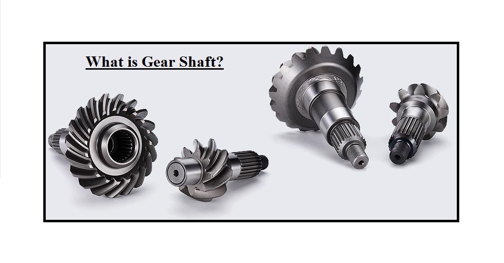
A gear shaft with the gearing curves at each section is introduced as intersecting shaft gears. Spiral Bevel gears are common examples of the gear profiles used on these forms of accurate-made shafts.
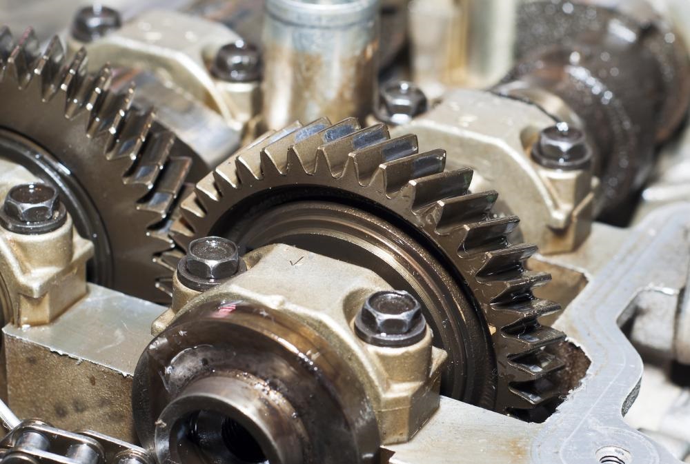
In their most common format, gears are toothed, round instruments enabling the transformation of engine speed into torque. Gears are either connected to or are a section of a gear shaft. Many of the more typical gears will include a hole in their center, introduced as a bore through which the gear shaft is mounted. Once the gear shaft is circulated, the gear also moves.
Fundamentally, the gear shaft is the axle of the system, supplying the rotation that permits one gear to engage with and turn another. The procedure is always known as gear reduction and is vital to transmitting horsepower from the engine to the drive controller. The transformation of the engine speed into the torque is what supplies the driving load powering, for instance, the wheels of an automobile.
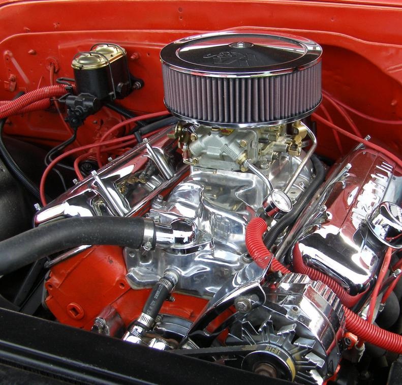
Along the shafts and gears in an automobile conversion, the engine can perform at a constant speed, whereas the auto wheels can be operated slower or faster, or even in reverse, employing the identical engine rotational speed and direction.
The flywheel of the normal automobile engine is attached to a gear shaft connecting a number of various-sized gears. Across the horizontal motion of the shaft, these basic gears are engaged with, and disengaged from other smaller and larger gears, also connected to the gear shafts. Likewise, the drive shaft, which delivers energy from the gearing in an automobile conversion to the axle and on to the drive wheels, is one typical example of using a gear shaft.
Gear shafts may include gear teeth integrated into the system, so becoming a shaft gear. Such shafts with gearing at each section are called intersecting ones. Bevel and spiral gears are intersecting forms of shaft gears. A common application of using this type of gearing is the rotor in a helicopter. A vertical intersecting type from the engine engages one or more horizontal shafts to rotate the rotors.

The same function applies to an automobile. The driveshaft is always a shaft at the transmission section and an intersecting shaft at the differential side. This arrangement allows vertical motion to be transformed into a horizontal output.
The Ultimate Guide to the Types of Gearbox
Types of Gear Shaft
Some various types of gear shafts are coupling-gear shafts, eccentric shafts, keyed shafts, and splined shafts. Gears employed in a heavy-duty case will most probably be made from sturdy metal. Other substances used to produce these shafts are plastic and copper-aluminum alloy. The basic gear shaft, typically found with the medieval grinding wheel, was made of wood.
Gear Shaft Working Principle
Gears are mechanical, toothed transmission parts used to transmit power and motion between machine sections, and in this post, we explain the various forms of gear shafts available and how they operate. Performance in mated pairs is determined by gears mounted on their teeth and the teeth of another facing gear or toothed part which avoids slippage.

Each gear or toothed part is connected to a machine shaft or base section, so once the driving gear (i.e. the gear that supplies the initial rotational input) circulates along with its shaft section, the driven gear (i.e. the toothed component or gear which is affected by the driving gear and provides the final output) rotates or transforms its shaft component.
Due to the modeling and structure of the gear pair, the transference of moving between the driven shaft and the driving shaft can cause a variation of the rotation direction or movement direction. In addition, if the gears do not have the same sizes, the system or machine experiences a mechanical advantage that permits a modification in the output torque and speed (i.e. the load which results in an object rotating).
Gear shafts and their mechanical features are broadly used throughout the industry to convert motion and power in a variety of mechanical instruments including clocks, instrumentation, and equipment, and to decrease or increase torque and speed in a variety of motorized instruments including motorcycles, automobiles, and machines.
Other design properties including gear shape, construction material, gear pair configuration, and tooth construction and design, help to define the different types of gear shafts available. Each of these gear shafts provides several advantages and behaviors, but the specifications and requirements demanded by a specific motion or power transmission case identify the type of gear shaft most suitable for the application.
We have already focused on gear shafts, exploring the different types available and explaining their respective mechanisms and performances in this post. In addition, this post outlines the selection criteria and typical applications for each type of gear shaft.
Designing and Specifying a Gearbox and Gear Shaft
The right gearbox modeling can influence efficiency, operation, reliability, and price. Each gearbox consists of four main parts: the output shaft, the input shaft, bearings, and gears. The gear shafts are supplied by the bearing which decreases friction. There can be hollow bore shafts or solid shafts. A system with a hollow bore permits the use of various shaft diameters, shaft lengths, and shaft materials.
Gears are an essential part of gearboxes since they transfer energy from one shaft to another. Due to the size of the system, the gear ratio, or the ratio between the values at which the first and last gears move, will modify. If the gear ratio is larger than one, the output shaft rotates at a slower speed than the input one. The opposite is possible if the gear ratio is less than the definition.

When designing a gearbox to meet your requirements, it’s considerable to keep these parts in mind, as well as the intended case. To get the most appropriate longevity and efficiency from your system, notice these criteria:
Main Specifications
Due to the intended application, the basic specs will change. The specifications that can be defined are backlash ratings and ratios. Most gearboxes have ratios varying from 1:1 to 120:1, but this can be larger if required. Likewise, most gearboxes have backlash ratings of smaller than 1 degree (or 60 arc-minutes). They can be modeled with low backlash, or smaller than 4 arc minutes.
Duty Cycle
A common full-time duty cycle for a system including gear shaft is 8 to 12 hours for 5 days a week, but this can be changed for application demands. Some cases need a low duty cycle, which would influence the size of the device. Smaller systems can be applied in certain conditions to allow for low duty cycles without decreasing life or destroying the teeth.
Environment
The temperature and overall environmental conditions that the system will be functioning in will influence its gear shaft construction. Due to the temperature, special oil or grease may be needed. For instance, in an environment of -20 degrees Celsius or below, particular grease is required to tolerate the low temperature. Humidity also affects the structure, and wash-down and salt-water applications will need a system that is better sealed against moisture.
Input and Output Needs
Shafts, bores, and output motion can be varied to meet your demands. Gear shafts and bores can be made in square, hex, D, and Splined forms if required. The output motions can be produced clockwise or counterclockwise and can even be dual-form motion shafts.
Advantages of Gear Shaft Manufacturing
- Gear profiles contain zerol bevel gears, straight bevel gears, and spiral gears.
- Their structure can be designed for highly efficient motion monitoring and power conversion between intersecting shafts at an angle.
- They are perfect for cases that need a speed/strength operation capacity and the capability to vary the angle of power flow.
Materials for Gear Shaft Manufacturing
- Carbon Steel
- Acetal
- Alloy Steel
- Delrin
- Brass
- Aluminum
- Bronze
- Nylon
- FLEXOR
- PEEK
- Plastic
- Stainless Steel
Applications of Gear Shaft in Gearboxes
- Construction
- Automotive
- Electrical
- Defense
- Heavy Equipment
- Electronics
- Industrial Machinery
- Medical Devices
- Marine
- Pneumatics
- Off-Highway
- Services
- Robotics
- Balancing (video)
- Carburizing
- Broaching
- Forging
- CNC Machining
- Grinding
- Heat Treating
- Gun Drilling
- Keyways
- Honing
- Spline Forming
- Shaping
- Threading
For example, visit here to see the application of a gear shaft in balancing a gearbox.
Gear Shaft Selection Considerations
Gear shafts are used in a variety of mechanical instruments, and, consequently, several various kinds and models are existence. The suitability of each form of gear shaft and its precise design for a power or motion transmission application is based on the requirements and features of the application. Some of the principal characteristics which may be considered when modeling and choosing a gear shaft include:
- Operational and environmental conditions
- Dimensional restrictions
- Transmission requirements
- Design standards
- Costs
Operational and Environmental Conditions
The operational conditions of the gear shaft application mainly affect the optimal kind and design of gear as the situations can affect the gear’s operation and durability. Some of the operational states which may affect a gear shaft are the noise and vibration created, the amount of weight applied, and friction and stress that happened on the teeth, while some of the environmental states which may influence a gear shaft contain humidity, temperature, sanitation, and cleanliness.
These situations affect a variety of gear shaft design factors including the surface treatments, construction material, and lubrication type and method.
Gear Shaft Surface Treatments
Some of the surface treatments existence for gear shafts are grinding and heat treatment.
Grinding down the plane of the gear teeth can reduce the amount of noise generated during function, improve the amount of power that can be transferred, and affect the gear’s accurate classification. Although, grinding also increases the overall price of production.
There are multiple heat treatment services present for gear shafts containing surface tempering, hardening, annealing, normalizing, and carburizing. These methods can influence the features of the gear material, such as increasing its strength and hardness, which can enhance the gear shaft’s overall longevity and durability.
Gear Shaft Construction Material
Gear shafts exist in a variety of construction materials including fiber, cast iron, nylon, steel, and stainless steel with each of these substances providing particular operational and manufacturing advantages.
For example, cast iron is employed for its ease of production and low cost, which make it desirable for large-scale or high-volume production cases which do not need high precision features.
Steel, such as alloy and carbon steel, is applied for its high tensile strength and hardness, which make it appropriate for creating highly durable gear shafts.
Nylon is a low-cost substance with lightweight and non-corrosive features, which make it suitable for the huge-scale generation and light-load cases.
Gear Shaft Lubrication
If properly and adequately applied, gear shaft lubricants can help to improve the overall lifespan of gear by reducing the fatigue and stress experienced by the gear teeth and body. Both the lubrication method and optimal kind of lubricant are dependent on the specifications and requirements of the application.
When choosing a lubricant, the load pressure capacity, potential lubricant’s viscosity, thermal and chemical stability, anti-foaming, water separating, and corrosion resisting properties within the performance and environmental conditions of the case should be considered. Given the use of the suitable lubricant, some of the advantages are the mitigation of heat produced, reduction of friction between gear teeth, and decreasing the amount of vibration and noise created during the function.
When an appropriate lubricant is chosen, it should be properly applied. The suitable application of a lubricant is based on a variety of features including the working speed and load. The most usual application methods for gear shaft lubrication contain splash lubrication, grease lubrication, and forced oil circulation lubrication.

- In splash type, the motion of the gears distributes the lubricant through the gear device sections. This lubrication approach is desirable for enclosed gear configurations which perform at higher speeds and with larger forces than grease lubrication. Although, precise oil rates and temperatures should be maintained.
- Grease (rather than oil) is used directly to the gear shaft and other sections in grease lubrication. The viscosity of this material allows it to supply lubrication for a long time before wearing off or breaking down. This lubrication approach is most appropriate for enclosed or open gear systems working at low speeds and with light powers.
- The lubricant is applied to the teeth directly with an oil pump in the forced circulation method, which delivers the lubricant to certain parts by spraying, dropping (using piping), or misting it into place. Whereas this approach is mainly effective, particularly for high-speed or heavy-duty cases, it is also more costly than other ways because of the number of parts needed for a complete system.
Dimensional Restrictions
Beyond the environmental and operational conditions of the application, gear shafts and their modeling are also restricted by the dimensional factors e.g. physical space of the mechanical system.
For instance, gears are commonly mounted on the center distances between the system shafts although some cases may need regulation of the center distances to better set within the dimensions of the mechanical machine, which requires a profile shift (i.e. deviation from the normal tooth profile). This deviation from the typical profile commonly means adjusting—either decreasing or increasing—the tooth’s thickness. This regulation varies the center distance, as well as the strength of the teeth.
Transmission Requirements
Gears are used to transmit the torque and motion between machine elements in mechanical systems. According to the construction and design of the gear shaft used, gears can vary the direction of motion and/or increase the output torque and speed. The features and requirements of the particular cases—i.e. whether they require to modify direction, increase torque or speed, or both—affect the required and optimal gear shaft form, modeling, and configuration.

Design Standards
There are a lot of specifications for systems using gear shafts. But unfortunately, no universal industrial tips exist which specify how a gear shaft should be modeled and created. Usually, gear shafts are constructed either to the norms set by the individual constructors or to suit the model and features of a special system or machine rather than those devices being modeled around a standard gear part.
The former case makes it more problematic to determine the appropriate gear type and model for an application among the standard parts existence from gear shaft manufacturers, whereas the latter case causes more problems and cost of finding replacements for the customized component.
Costs
When creating a custom gear, the cost of production is affected by multiple factors containing the construction material, gear design, precision standards, surface treatments and finishes, and lubricant and lubrication approaches. Industry professionals and procurements agents also require to notice the longevity and durability of the custom gear shaft to evaluate the optimal maintenance and replacement schedule.
It is necessary to select a gear shaft that efficiently meets the requirements of the case. However, it is also essential to keep in mind the total lifecycle costs—i.e. the gear repair, production, maintenance, and replacement costs—of the selected gear shaft to identify whether the system is worth the investment or not. For some cases, a typical, off-the-shelf gear shaft may meet the demands at a much lower price.


Thank you, we hope that it can encourage you to visit our other engineering posts.