A Potential Transformer is also introduced as a voltage step-down device or instrument transformer, or voltage transformers, in which the voltage of a circuit is dropped to a lower voltage for detection. The electromagnetic instrument applied for transforming the greater voltage of the network to the lower voltage is known as a potential transformer. The output of a low voltage network can be sensed with wattmeters or voltmeters. These are able to decrease or increase the voltage ratings of a circuit without a variation in its windings and frequency. The working principle and structure of a potential transformer are the same as the conventional and power transformers.
What is a Potential Transformer?
Transformers are the passive electromagnetic instruments that operate based on the principle of electromagnetic induction rules, which transmit electrical power from one circuit to another one magnetically. It includes two coils; one is the primary section, and the other is the secondary coil. Both the coils (windings) are magnetically combined without any magnetic part and electrically divided.
The transformer transmits the electricity (current/voltage) from one winding to another coil (coil) using a mutual induction. There is no variation in frequency during the energy transformation. Transformers are divided into two classes according to the core construction, like core types and shell types. They are also categorized into step-up and step-down transformers based on the voltage rating conversion and winnings. There are different forms of transformers applied in the AC networks, such as potential transformers, power transformers, autotransformers, and three-phase transformers. In this post, we will discuss potential transformers completely.
Definition
The potential transformer can be defined as an instrument employed to transmit the voltage from a higher value to a lower output. This transformer step down the voltage to a safe limit value which can be easily measured by the ordinary low voltage instrument like a voltmeter, wattmeter and watt-hour meters, etc.
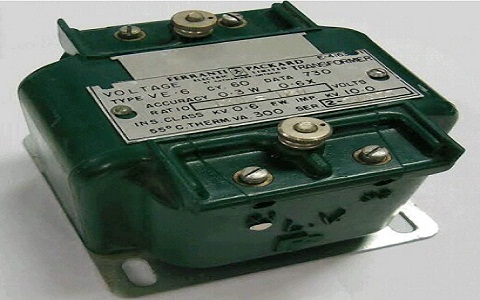
Circuit Diagram
The potential transformer contains primary winding with more twists and a secondary section with fewer turns. The great input AC voltage is presented to the primary section (or connected to the high voltage network to sense). The lower output voltage can be obtained through the secondary side using a voltmeter. The two windings are combined magnetically to each other without any attachment between them.
Potential transformers are produced with high quality to perform at low magnetic current, low flux density, and minimized load. While compared to a conventional type, it employs great conductors and an iron center. It can be constructed in the form of a shell type and core type to achieve the highest precision. Typically, core-type potential transformers are suitable to transmit the high voltage to the lower output.
It employs co-axial sections to decrease the leakage reactance. As the potential types are performed at high voltages, the great voltage primary section is divided into small parts coils/turns to decrease the insulation cost and problems. The phase shift between the output voltage and the input voltage should be controlled accurately to keep the lower voltage by changing the load. Windings layered with vanish cambric and cotton tape to decrease the insulation price.
Hard fiber separators are applied to cover the coils. Oil-filled bushings are also employed to send the high voltage outputs (above 7kV) to the basic lines. The primary section of a potential transformer has a great number of turns, while the secondary side has fewer turns. The voltmeter or multimeter is used to detect the lower output voltage.
Construction
The potential transformer is constructed with a high-quality core working at a low flux value so that the magnetizing current is low. The transformer’s terminals have to be constructed so that the change in the voltage rating with load is minimum and the phase shift between the output and input voltage is also minimum.
The primary section has a great number of turns, and the secondary side has a much small number of them. The co-axial arrangement is applied in the potential transformer for reducing the leakage reactance. The insulation price is also decreased by dividing the primary section into particular parts, which minimized the insulation between the layers.
Connection
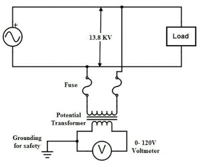
The potential transformer is arranged in parallel configuration with the circuit. The primary section of the device is directly attached to the power network, whose voltage should be monitored. The secondary terminals of the system are connected to the sensing instrument like the wattmeter, voltmeter, etc. The secondary section of the potential transformer is magnetically combined through the magnetic network of the primary windings.
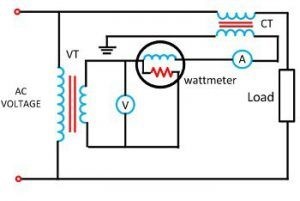
The main terminal of the device is rated for 400V to several thousand volts, and the secondary one is often rated for 400V. The rating of the primary voltage to the secondary one is known as the “transformation ratio or turn ratio”.
Types of Potential Transformer
The potential transformer is mainly categorized into two types, i.e., the conventional wound forms (electromagnetic form) and the capacitor voltage potential types.
Conventional Wound Potential Transformer
Conventional wound form is very expensive due to the demand of the insulations.
Capacitor Potential Transformer
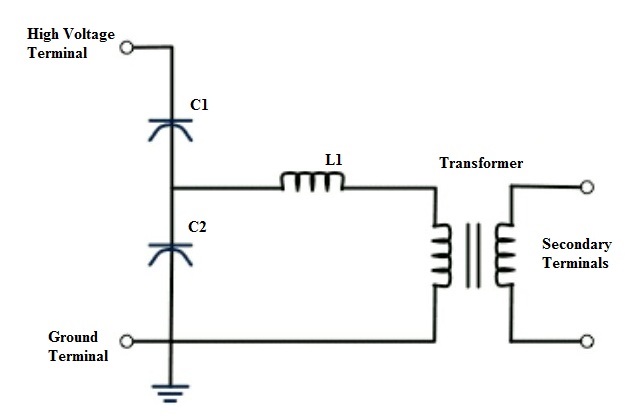
Capacitor potential type is a junction of a capacitor potential divider and a magnetic part of a relatively small ratio. The circuit diagram of the capacitor types is presented in the figure below. The stack of great voltage capacitors from the potential divider, the capacitors of two sides become C1 and C2, and the Z is the burden.
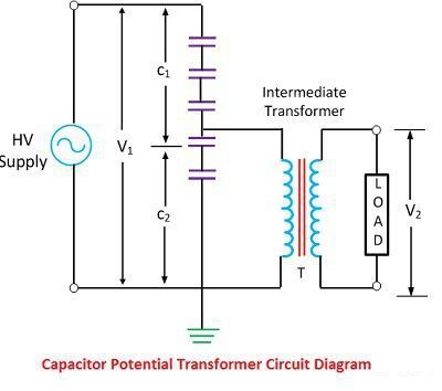
The voltage presented to the primary section of the intermediate transformer is usually of the order of 10kV. Both the intermediate transformer and the potential divider have the rating and insulation demand which are appropriate for economical construction.
The intermediate transformer should be of very low ratio error, and the phase angle provides the satisfactory performance of the complete set. The secondary terminal value is given by the formula presented below.
{V}_{2}={V}_{1}\times \frac{{C}_{1}}{{C}_{1}+{C}_{2}}
Potential Transformer Working Principle
The potential transformer attached to the power network whose voltage should be sensed is connected between the ground and the phase. That means the primary section of a potential transformer is attached to the high voltage network, and the secondary section of a transformer is connected to a multimeter. Because of the mutual induction, the two sides are magnetically joined together and operate on the principle of electromagnetic induction.
The reduced voltage is detected through the secondary side with respect to the voltage within the primary section using a voltmeter. Because of the large impedance in the system, the small current moves across the secondary side and performs similarly to the usual transformer with no or low power. Hence these kinds of transformers work at a voltage level of 50 to 200VA. Click here to explore more about the principle of a potential transformer.
Based on the convention transformer, the transformation ratio is
{V}_{2}={V}_{1}\times \frac{{N}_{2}}{{N}_{1}}
Where ‘V1’is the voltage of the primary winding, ‘V2’ is the voltage of the secondary side, ‘N1’is the number of turns in the primary section, and ‘N2’is the number of turns in the secondary side. The high voltage of a network can be identified using the above formula.
Potential Transformers Classification
Potential transformers can be classified into the following forms based on their function.
- Metering voltage transformers
- Protection voltage transformers
- Electromagnetic Potential Transformers
- Capacitive Potential Transformers
Protection Voltage Transformers
These exist in single or three-phase types and work with the highest accuracy. They are utilized to perform and monitor measuring instruments, relays, and other devices.
Electromagnetic Potential Transformers
These are the same as the primary transformer, where primary and secondary sections are wounded on a magnetic center. It operates based on a value of above or below 130KV. The primary section is determined based on the phase, and the secondary section is connected to the ground. They are employed in the relay, metering, and high voltage networks.
Capacitive Potential Transformers
These are also introduced as bushing type or coupling type capacitive potential transformers or capacitive potential dividers. The series arrangement of capacitors is attached to the primary or secondary sides. The output value through the secondary winding is detected. It is used for power cable carrier communication aims and is also more costly.
Errors in Potential Transformers
In the primary instruments, the output value on the secondary side is exactly related to the value of the secondary transformer. The voltage drops due to the resistance and reactance in primary and secondary in the potential transformers, and also the power coefficient on secondary results in the phase shift errors and voltage errors.
Ratio and Phase Angle Errors of Potential Transformer
The primary and the secondary value is accurately related to the primary voltage in an ideal potential transformer and precisely in phase opposition. But this cannot be obtained actually because of the primary and secondary voltage reduction. Therefore, both the primary and secondary value is introduced in the system.
Voltage Ratio Error
The voltage ratio error can be evaluated regarding the sensed voltage, and it is obtained by the formula as presented below:
Ratio_{Error}=\frac{{K}_{t}{I}_{s}-{I}_{p}}{{I}_{p}}
where Kt is the nominal ratio, i.e., the ratio of the rated primary value and the rated secondary value. If there is a difference between the complete voltage and practical voltage, then the voltage error happens. Percentage of voltage error can also be obtained by the equation below:
Voltage_{Error}=\frac{{V}_{p}-{K}_{t}{V}_{s}}{{V}_{p}}\times 100
Phase Angle Error
The phase angle error is a problem between the secondary section voltage, which is accurately in phase opposition with the voltage of the primary section. The increases in the number of devices in the relay attached to the secondary side of the potential transformer will rise the errors in the potential transformers.
If there is a basic difference between the phase angle of the primary value ‘Vp’ and the reverse secondary value, the phase angle error happens.
The burden of a Potential Transformer
The burden is the overall external volt-amp power on the secondary section at the rated voltage. The rated burden of a potential transformer is a VA burden which should not be increased if the device tends to perform with its rated precision. The rated burden is determined on the nameplate.
The maximum or limiting burden is the highest VA power at which the practical transformer will constantly perform without overheating its parts beyond the permissible range. This burden is several times higher than the rated burden.
If the standard ratio of the potential transformer is varied from the practical ratio of the device due to the resistance and reactance drops, then this error will occur.
Causes of Errors
Because of the internal impedance, the voltage reduces in the primary section, and it is transmitted proportionally to its twists ratio and the secondary section. Similarly, the same thing occurs on the secondary side.
Reduction of Errors
The errors of potential transformers can be decreased or prevented by increasing the precision in the designing, magnitudes of resistance and reactance of primary and secondary sides, and minimum magnetization of the core.
Phasor Diagram of a Potential Transformer
The phasor diagram of a potential transformer is presented in the figure below.
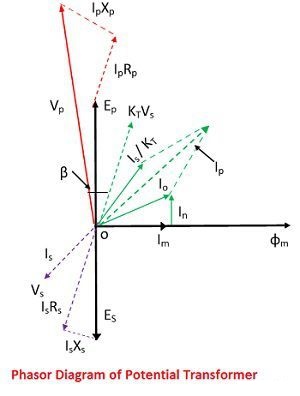
Where,
- Es – Secondary induced emf
- Is – Secondary current
- Xs – Secondary winding reactance
- Rs – Secondary winding resistance
- Vs – Secondary terminal voltage
- Vp – Primary terminal voltage
- Ip – Primary current
- Ep – Primarily induced emf
- Xp – Primary winding reactance
- Rp – Primary winding resistance
- Kt – Turn ratio
- Im – Magnetizing component of Io
- Io – Excitation current
- Iw – Core loss component of Io
- Β – Phase angle error
- Φm – Main flux
The main flux is considered as the reference. The primary value is the vector sum of the excitation current Io, and the current identical to the reversal secondary value Is improved by the ratio of 1/kt in the instrument transformer. The Vp is the voltage provided to the primary side of the potential transformer.
{I}_{P}=\frac{{I}_{O}+{I}_{S}}{{K}_{t}}
The voltage reduces based on the resistance and reactance of the primary section due to the primary current, which can be obtained by IpRp and IpXp. When the voltage reduction subtracts from the primary value of the potential transformer, the primarily produced EMF (Electromotive Force) will appear through the terminals.
This basic EMF of the device will change into the secondary side by the mutual induction effect and transformed into the secondary produced EMF (Es). This EMF will reduce by the secondary side reactance and resistance, and the resultant output will appear through the secondary terminal voltage, and it is expressed by Vs.
The produced primary voltage EMF is the subtraction of reactance and resistance drops (IpXp, IpRp) from the primary voltage (Vp). The voltage reduces because of the resistance and reactance of the primary winding.
The EMF produced in the primary is transmitted into the secondary side by the mutual induction and creates the EMF in the secondary side (Es). The output voltage through the secondary side because of the EMF reduction by the reactance and resistance is Vs. The output value on the secondary side is gained by subtraction of the resistance and reactance drops (IsRs, IsXs) from the produced EMF in the secondary winding (Es).
Applications of a Potential Transformer
The applications of a potential transformer are listed below:
- Used in metering and relay circuits
- Uses in power line carrier communication networks
- Used in protection devices electrically
- Used for the protection of impedance in different applications like the generators
- Used for protecting feeders
- Used as protection voltage transformers
- Used in synchronization of feeders and generators
Advantages of a Potential Transformer
The advantages of a potential transformer are summarized below:
- Ammeter and voltmeter can be connected to control high current and voltage, respectively.
- Irrespective of the sensing of voltage or current, the level of the low range meter can be configured with the help of a potential transformer.
- The operation of these instruments is utilized for working in many forms of protecting devices such as the relays and pilot lights.
- A single potential transformer can be used to control several instruments.
Disadvantages of a Potential Transformer
Due to the efficiency of the device, there are not several drawbacks. The main disadvantage of a potential transformer is that it holds this configuration limited to only AC networks and cannot be used on the DC circuits.
Conclusion
The potential transformers are mainly employed in the protecting relaying system since the potential windings of the protective instrument are not directly connected to the network in the case of the high voltage. As a result, it is essential to step down the input voltage and also to insulate the protective system from the primary network.
Read More In Linquip
- Difference between Power Transformer and Distribution Transformer
- What is Electrical Transformer?
- What is Auto Transformer? Advantages & Application
- What is a Distribution Transformer?
- What is the Efficiency of Transformer?
- What is Step-Down Transformer and Its Application?
- What is a Single Phase Transformer?
- What is Power Transformer?
- What is the Current Transformer?
- What is the Equivalent Circuit of Transformer?
- Types of Transformer: An Article About How Transformers Differ in Construction and Design
- What is Step Up Transformer?

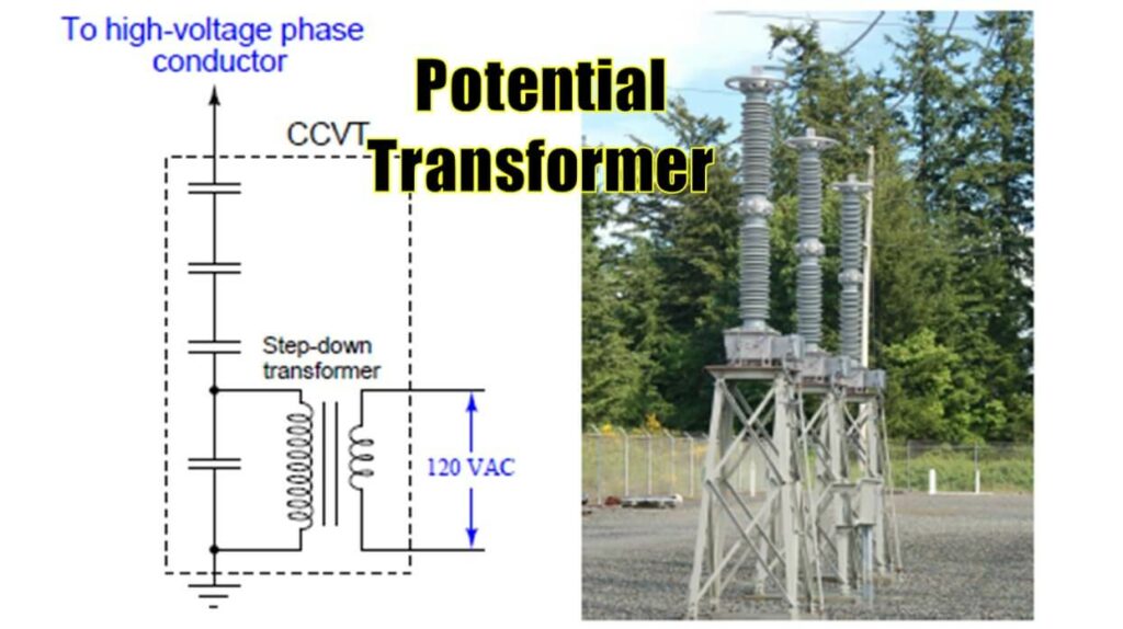


I have one PT and have two harmonic filters that need the line voltage. they both need to be connected to the 120V output of one PT. Both Filter inputs have the shorting switches and none accessible at the PT. Is there any way to wire this in series or parallel safely and needing an accurate 120V without adding a second PT?
If I put shorting switches at the PT can I parallel out to both inputs to the harmonic filters? Or would it have to be in series?
Thanks for visiting our website, Dave! Linquip offers hundreds of experts in the field of electrical engineering. You can visit our experts page and find suitable persons to ask your question.