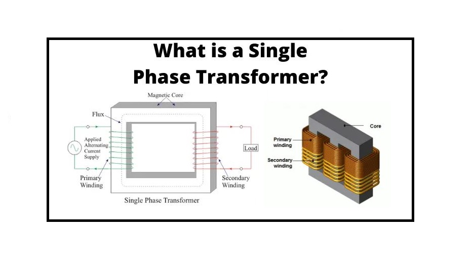
A single phase transformer is an electrical instrument that uses single-phase A.C input and provides single-phase A.C. This is employed in the distribution of energy in non-urban regions as the overall demand and prices involved are lower than the 3-phase type of transformers. They are utilized as a step-down device to reduce the home voltage to an appropriate amount without a variation in frequency. For this reason, it is typically employed to power electronic instruments at residences. This post discusses an overview of a single phase transformer.
A single-phase transformer is a transformer that uses just one phase of electricity. A transformer is a passive electrical device that uses electromagnetic induction to transmit electrical energy from one circuit to another. The single-phase transformer is a vital component of many industrial systems. Single-phase transformers are available from a variety of Suppliers and Companies, as well as various manufacturers and distributors, and there are several Single Phase Transformers for Sale on Linquip.
There is a comprehensive range of transformer services on the Linquip platform that meets all of your needs. Linquip can connect you with a number of industrial transformer service companies and experts who can help you. Linquip offers a team of Transformer Specialists who can assist you evaluate your device.
What is a Single Phase Transformer?
Definition
A transformer is an instrument that transforms magnetic power into an electrical type. It has two electrical sections introduced as the primary and secondary windings. The primary section of the device receives power, whereas the secondary winding delivers energy. A magnetic iron circuit introduced as the “core” is typically used to wrap around these sections. While these two coils are isolated electrically, they are linked magnetically.
Once an electric current passes across the primary winding of a transformer, then a magnetic field is produced, which induces a voltage within the secondary part of a transformer. The single phase transformer is employed to either step down or step up the voltage at the output based on the type of application. This transformer is commonly a power transformer with great efficiency and low wastes. The single phase transformer schematic is presented below.
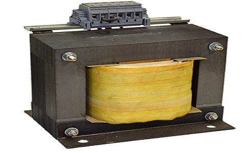
A single phase transformer is a particular form of transformer which performs based on single-phase power. This instrument is a passive electrical device that transmits electrical power from one circuit to another across the process of electromagnetic induction. It is most typically employed to decrease (‘step down’) or increase (‘step up’) voltage levels between circuits.
A single phase transformer includes a magnetic iron core serving as a magnetic component and a cooper winding serving as an electrical part.
Principle
The single-phase transformer operates based on the principle of Faraday’s induction law of Electromagnetic. Generally, the mutual induction between secondary and primary windings is responsible for the working of the transformer in an electrical transformer.
This transformer is a high-efficiency part of electrical equipment, and its wastes are very low since there isn’t any mechanical friction involved in its function.
Transformers are used in almost all electrical networks from low voltage up to the largest voltage rating. They perform only with alternating current (AC) since direct current (DC) does not produce any electromagnetic induction.
How does a Single Phase Transformer Work?
A transformer is a static instrument that transmits electrical energy from one circuit to another one with a similar frequency. It has primary and secondary windings. A transformer performs based on the principle of mutual inductance.
When the primary section of a transformer is combined with an A.C source, the current moves in the coil, and the magnetic field created. This state is introduced as mutual inductance, and the current flowing is as per Faraday’s induction law. As the current rises from zero to its maximum amount, the magnetic field improves and is obtained by dɸ/dt.
This electromagnet creates the magnetic environment of force and expands outward from the coil generating a path of magnetic flux. The turns of both parts get linked by this magnetic field. The strength of a magnetic field produced in the core is based on the turn number in the winding and the value of current. The current and the magnetic flux are directly related to each other. Click here to see the working principle of a single phase transformer completely.
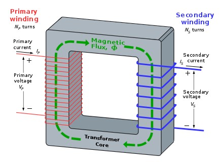
As the magnetic lines of flux move around the center part, it passes across the secondary section, inducing voltage through it. Faraday’s Law is applied to evaluate the voltage induced within the secondary coil, and it is obtained by:
V= N \frac{d\Phi }{dt}
where,
‘N’ is the number of turns around the coil
The frequency is identical in both primary and secondary windings.
Therefore, we can say that the voltage produced is the same in both sections as the same magnetic flux links both the components together. Also, the whole voltage induced is directly related to the number of turns in the coil.
Let us propose that the primary and secondary sections of the transformer include single turns on each. Assuming no wastes, the current moves across the coil to generate magnetic flux and induce voltage of one volt through the secondary section.
Due to the AC source, magnetic flux changes sinusoidally, and it is obtained by:
\Phi = {\Phi }_{max} sin (\omega t)
The relationship between the produced emf, E in the coil windings of N turns can be obtained by
E= N \frac{d\Phi }{dt}
E = N\omega {\Phi }_{max} cos (\omega t)
{E}_{max} = N\omega {\Phi }_{max}
{E}_{rms} = N\omega\sqrt{2} {\Phi }_{max}=2\pi \sqrt{2} f N {\Phi }_{max}
{E}_{rms} = 4.44 f N {\Phi }_{max}
Where,
- ‘f’ is the frequency in Hertz, obtained by ω/2π.
- ‘N’ is the number of coil turns
- ‘ɸ’ is the value of flux in Webers
The above formula is introduced as the transformer EMF Equation. “N” will be the number of primary turns (NP) for EMF of a primary part of a transformer E, whereas, for the emf, E of a secondary section of a device, the turn number, N will be (NS).
Single Phase Transformer Parts
Single phase transformer parts include windings, core, and isolation. The windings should have a low resistance amount, and commonly, they are constructed of copper (hardly ever of aluminum). They are layered around the core and should be isolated from it.
Also, the turns of the winding should be isolated from each other. The transformer center is constructed of very thin steel covers which have large permeability. These covers should be thin (between 0.25 mm and 0.5 mm) due to the reduction of power wastes (introduced as eddy current losses).
They must be isolated from each other, and commonly, the insulating varnish is applied for that aim. The transformer insulation can be supplied as a liquid-filled or dry type. The dry-type insulation is supplied by air, synthetic resins, gas, or vacuum. It is employed just for little-size transformers (below 500 kVA). The liquid insulation form commonly means applying mineral oils.
The oil has a long life span, overload capability, appropriate isolation features, and also supplies transformer cooling. Oil insulation is often utilized for big transformers.
The single phase transformer includes two windings, one on the primary section and the other on the secondary part. They are mainly employed in single-phase electrical power networks.
The three-phase system application means employing three single-phase sets arranged in the three-phase network. This is a more expensive method, and it is applied in the high-voltage power network.
Construction of Single Phase Transformer
A simple single phase transformer includes each winding being layered cylindrically on a soft iron part separately to supply a necessary magnetic circuit, which is typically introduced as the “transformer core”. It provides a path for moving the magnetic field to induce voltage between two sections.
The two sections are not close enough to have a sufficient magnetic coupling. Therefore, increasing and converging the magnetic circuit near the coils can improve the magnetic coupling between primary and secondary sections. Thin steel covers shall be employed to avoid power wastes from the core.
The transformer construction is classified into two types according to how the windings are wound around the main steel laminated core.
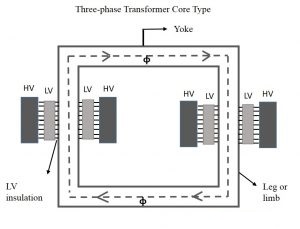
Core-type
In this form of production, only half of the windings are layered cylindrically around each part of a transformer to improve magnetic coupling, as presented in the figure below. This form of construction guarantees that the magnetic path of force flows through both the windings simultaneously. The noticeable disadvantage of the core-type transformer is the leakage flux that happens based on the flow of a low proportion of magnetic lines of force outside the device.
Shell-type
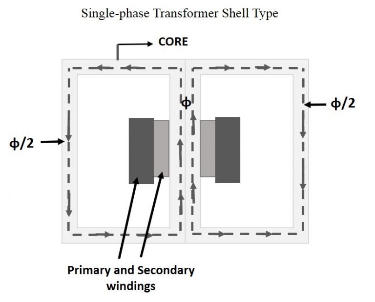
In this form of structure, the primary and secondary sections are installed cylindrically on the center core resulting in twice the cross-sectional region than the outer parts. There are two near magnetic paths in this kind of construction, and the outer leg has the magnetic flux “ɸ/2” moving. Shell-type device overcomes the leakage flux, decreases core wastes, and improves efficiency.
Single Phase Transformer Types
The following types of transformer are typically constructed to receive and output single-phase AC power.
Audio Transformer
This type removes ground noise from audio signals by supplying the device with magnetic shielding.
Autotransformer
They are commonly employed in low power systems to connect circuits with various voltage classes. It consists of only one winding, cannot isolate networks, and is typically lighter, smaller, and cheaper than other types. The voltage supply and electrical load are joined to two taps, and voltages are specified by tapping the winding at several points. An autotransformer with a regulated tap is introduced as a variable transformer or a variac.
Buck-Boost
In this type, the transformer regulates a voltage rating to device specifications. They are generally utilized as circuit isolators.
Constant-Voltage Transformer (CVT)
This type creates a relatively constant output voltage, despite practically great variances in the input voltage.
Constant-Current Transformer (CCT)
They are also called a regulator; it includes a self-regulating secondary section that supplies a consistent output current for any load through its dynamic level. It is usual for streetlight cases.
Distribution Transformer
This is the pole-mounted, oft-seen device that steps down current for light-duty electrical cases.
Flyback Transformer
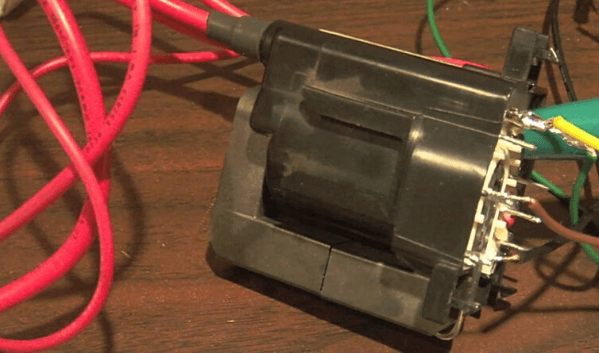
This type can be used to create a high-voltage output, and the transformer saves power in its magnetic sections for a short time.
Generator Step-up Transformer
It can step up voltage rating to an appropriate long-distance transmission voltage rate.
Harmonic Mitigating Transformer
This form utilizes electromagnetic flux cancellation, phase-shifting, and source impedance to reduce the harmonic currents in distribution networks, which eventually decreases the transformer operating temperature.
Impedance-Matching Transformer
These are applied to reduce the signal reflection from electrical power and always have a 1:1 turn ratio. A typical example of an impedance-matching type would be a balun, which is utilized to combine two circuits of mismatched impedance, like a regulated line of two conductors carrying similar currents in opposite directions that are attached to an unbalanced path of one conductor carrying the load.

Industrial Control Transformer
They provide power to constant-voltage or constant-current instruments that may be susceptible to changes in the electrical source, like relays, solenoids, or other electromechanical instruments.
Interface Transformer
They can isolate communication signals.
Isolation Transformer
It is not employed to step down or step up voltages but rather to buffer networks from each other.
Leakage Transformer (Stray-Field Transformer)
It can maintain a great leakage inductance by weakly coupling the magnetic fluxes of the secondary and primary sections. This makes the device short-resistant, an important feature of transformers for welding functions.
Lighting Transformer
It can supply low voltages for lighting and other light-duty cases.
Medical Transformer
High potential requirements, leakage current, temperature condition, and current and thermal fusing are the primary concepts of medical transformers based on the sensitive surrounding in which they are used. They are carefully adjusted by industrial and law standards.
Multi-Ratio Transformer
This is single phase transformer with different outputs, with each output tap corresponding to a different rating.
Neutral Grounding Transformer
This type protects generators and power transformers from harmful fault currents. A voltage is stimulated in the open delta when a fault happens, and there is a voltage reduction in the connected resistor.
Power Transformer
It can transform voltages from one rating or phase to another for widespread energy distribution.
Rectified Transformer
Using to convert AC to DC.
Resonant Transformer
A capacitor is located within one or both windings to operate so that the network can be tuned.
Solar Power Transformer
The transformer can be used as a component of a single-phase string inverter or as a step-up device to connect PV plants to a network.
Substation Transformer
It is a step-down device that transforms transmission-level voltages to distribution-level output.
Mounting a Single Phase Transformer
The overall weight and size of a transformer finally identify how it should be installed. However, some characteristics help us for mounting a single phase transformer, including:
- Chassis: integral components enable the device to be set via fasteners.
- Chip: commonly constructed with thin-film technology, these devices are incorporated into integrated networks and are always used as isolators.
- Dish/disk: toroidal core types can be mounted with hardware that consists of a bolt within the middle of the torus.
- H-frame: a mounting form that mitigates the influences of the shock and vibration.
- Modular jack: typically, a modular junction with a built-in transformer.
- Pad: the transformer is located on a structural basis, such as substation transformers installed on a concrete pad.
- PC/PCB: also introduced as board-mount types, these transformers transmit voltage between two networks for circuit board cases. They include core, windings, casing, a mounting method (surface mount or through-hole), and connection terminals. Some PCB types are ICs constructed via semiconductor processing.
- Pole: these ubiquitous transformers installed on roadside utility poles step down the input from localized transmission rating to the residential- and commercial-suitable voltages.
- Skid/Trailer: massive transformers can be simply relocated to meet changing electrical requirements. They incorporate non-permanent increases in local electrical needs.
Specifications of a Single Phase Transformer
The accompanying features are important when discussing a single phase transformer.
- Operating frequency rating: transformers with high operating frequencies are smaller since fewer sections are required to match impedances.
- Primary voltage level: It means the input voltage rating; different nominal voltages represent more than one primary section.
- Secondary voltage rating: It means the output voltage range.
- Secondary current level: determines the rated output current
- Power rating (VA): maximum voltage desirable for a system, presented in volts-amps (V.A).
- Operating temperature: safe temperature level of a system in its function; transformer temperatures increase while in utilization.
Features of a Single Phase Transformer
Some important features of a single phase transformer are summarized below:
- Current limiting protection: an overcurrent protection process.
- Flameproof: the transformer fire resistance is too important, which is beneficial in potentially reactive environments like mines.
- NEMA enclosure: the device casing or container adapts with a NEMA level, a normal regarding ingress protection for different industrial and environmental contaminants.
- Indoor/outdoor rated: the device is determined for certain working environments. Oil-filled types are almost often installed outside.
- Waterproof: transformer includes a sealed side to prevent water intrusion.
- Submersible: device can be submerged.
Applications of a Single Phase Transformer
The main advantages of a single-phase unit are maintenance, transportation, and spare unit availability. The single-phase transformers are broadly employed in commercial low voltage cases such as electronic devices.
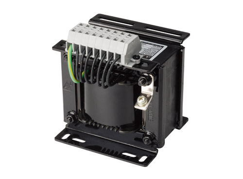
They perform as a step-down voltage device and reduce the home voltage amount to the value desirable for electronics supplying. A rectifier is typically connected to convert an AC voltage to the DC type, which is employed in electronics cases on the secondary side.
Other applications of a single phase device are summarized below:
- To step-down long-distance signals to supply both light-commercial and residential electronic devices
- In television sets for the voltage adjustment
- To step up energy in home inverters
- To support power to non-urban regions
- To isolate two networks electrically as primary and secondary are installed far from each other.
Download single phase transformer PDF
Read More In Linquip
- What is Electrical Transformer?
- What is Auto Transformer? Advantages & Application
- Working Principle of Transformer: Discover the Mechanism Involved in the Operation
- Difference between Power Transformer and Distribution Transformer
- What is the Efficiency of Transformer?
- What is Step-Down Transformer and Its Application?
- Difference Between Step Up and Step Down Transformer
- What is Step Up Transformer?
- What is a Distribution Transformer?
- What is a Single Phase Transformer?
- What is Power Transformer?
- Current Transformer Types and Applications
- What is the Current Transformer?
- What is Potential Transformer?
- Construction of Transformer: Uncover The Parts and Construction
- What is the Equivalent Circuit of Transformer?
- EMF Equation of Transformer- Turns Voltage Transformation Ratio of Transformer
- Difference Between Step-Up and Step-Down Transformer: A Quick Guide
- Types of Transformer: An Article About How Transformers Differ in Construction and Design

