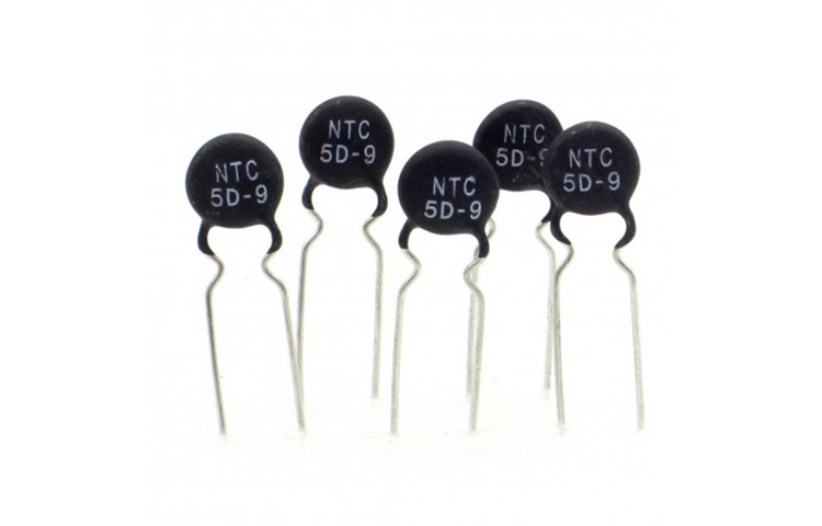
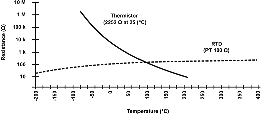
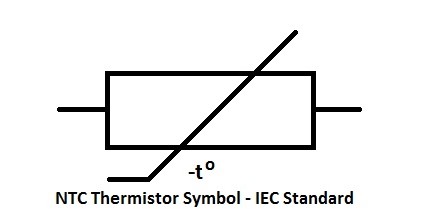
What is NTC Thermistor- The term “NTC” is the abbreviation for “Negative Temperature Coefficient”. In NTC thermistors, the resistance decreases as temperature increases, so they are resistors with a negative temperature coefficient. In addition to serving as resistive temperature sensors, they are also used as current-limiting devices. There is a five-fold increase in temperature sensitivity coefficient over silicon temperature sensors (silistors) and a ten-fold increase over resistance temperature detectors (RTDs). NTC sensors are typically used in a range from −55 to +200 °C.
With Linquip, you can learn everything you need to know about thermistors. We have a “Thermistors” page where you can find more information about Linquip’s solutions regarding your specific situation. The time has come for you to learn about NTC thermistors so you can simplify your work.
Choosing the right thermistor can be difficult if you are unfamiliar with them. Among our extensive selection of Thermistors Products on the Linquip website, you will find many options. The Linquip Platform allows you to receive free quotes from multiple Thermistors Suppliers and Companies.
There are several types of thermistors, but the most common is a negative temperature coefficient thermistor. Often small in size, these temperature sensors are highly sensitive. This guide will teach you everything you need to know about NTC thermistors in detail.
A Brief History
In 1833, Michael Faraday discovered the first NTC thermistor, which was based on the behavior of silver sulfide semiconductors. He observed a dramatic reduction in silver sulfide resistance with increasing temperature. Due to the difficulty in creating the initial thermistors and partial applications of the technology, commercial production of thermistors did not begin until the 1930s.
Samuel Ruben invented a commercially viable thermistor titled “Duracell” in 1930. A major development occurs in the study of NTC thermistors due to the development of incessant transistor technology after that. 1960 marked the development of NTC thermistors.
Working Principle of NTC Thermistor
Temperature is the main factor affecting the operation of an NTC thermistor. A thermistor’s resistance will decrease as its temperature increases. Every 1-degree centigrade increase in temperature will result in a 5% decrease in resistance.
Material resistance to electrical flow is influenced by two factors: how many free electrons there are and how easily electrons can move through it. In the case of the latter, the crystal composition of the material will affect how many “free electron paths” there are for the current to flow.
These thermistors are made up of ceramics containing metal oxides, including oxides of Mn-Ni-Co, Ni-Cr, and Cu-Ni. Combined with oxygen, these metals create bonds that restrict electron paths within the crystal structure, thereby increasing resistance.
The crystal structure of metals breaks down slightly at higher temperatures due to collisions between atoms, releasing electrons, and allowing free electrons to travel. When there are more free electron paths, there is less resistance to electrical flow. In other words, NTC thermistors show a reduction in resistance with increasing temperature.
Characteristics of NTC Thermometers
Temperature changes and self-heating cause NTC thermistor resistance to change. In this case, ambient heating refers to any heat source external to the NTC Thermistor. By passing an electric current via the thermistor, joule heat results in self-heating. “No-load” characteristics are characterized by a low self-heating influence.
No-Load NTC Thermistor
Resistance-Temperature Characteristics
Within the operating temperature range of an NTC thermistor, an exponential function approximates the relationship between resistance value and absolute temperature.
R_1=R_2.{\mathrm{exp} \left(B.\left(\frac{1}{T_1}-\frac{1}{T_2}\right)\right)\ }
R1 and R2 are NTC Resistance in Ω at temperatures T1 and T2 in K. B value is considered in K as the Material Constant of the NTC thermistor. As a practical matter, a resistance-temperature relationship table will be provided within the NTC’s operating temperature range.
B Value
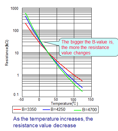
NTC materials determine B values, which are expressed as slopes on R/T curves. This is another way to express B based on the previous formula.
B=\frac{{\mathrm{lnR}}_1\mathrm{\ -\ }{\mathrm{lnR}}_{\mathrm{2}}}{\frac{\mathrm{1}}{{\mathrm{T}}_{\mathrm{1}}}\mathrm{-}\frac{\mathrm{1}}{{\mathrm{T}}_{\mathrm{2}}}}\mathrm{\ }
NTC materials typically have B values between 3000K and 5000K. It is important to balance B value selection with other constraints when selecting nominal resistance since every type and packaging of NTC will not support every B value.
Temperature coefficient
When the temperature changes, the resistance value is altered relative to the temperature coefficient.
\mathrm{\alpha }\mathrm{\ =}\frac{\mathrm{1}}{\mathrm{R}}.\frac{\mathrm{dR}}{\mathrm{dT}}\mathrm{\ }
Resistance Tolerance
An NTC thermistor’s resistance tolerance is specified at one temperature point, which is application specific, usually 25°C. Upon customer request, other temperatures can also be specified. The formula for expressing resistance tolerance is as follows:
\mathrm{\Delta }{\mathrm{R}}_{\mathrm{1}}\mathrm{\ =\ }\left|\frac{\mathrm{\partial }\mathrm{R}\left(\mathrm{T}\right)}{\mathrm{\partial }{\mathrm{R}}_{\mathrm{2}}}\right|\mathrm{.\ }\mathrm{\Delta }{\mathrm{R}}_{\mathrm{2}}\mathrm{\ +}\left|\frac{\mathrm{\partial }\mathrm{R}\left(\mathrm{T}\right)}{\mathrm{\partial }\mathrm{B}}\right|\mathrm{.}\mathrm{\Delta }\mathrm{B\ \ +}\left|\frac{\mathrm{\partial }\mathrm{R}\left(\mathrm{T}\right)}{\mathrm{\partial }\mathrm{T}}\right|\mathrm{.}\mathrm{\Delta }\mathrm{T\ }
This equation can be simplified as follows if the third temperature-dependent term is neglected:
\mathrm{|}\frac{\mathrm{\Delta }{\mathrm{R}}_{\mathrm{1}}}{{\mathrm{R}}_{\mathrm{1}}}\mathrm{|=|}\frac{\mathrm{\Delta }{\mathrm{R}}_{\mathrm{2}}}{{\mathrm{R}}_{\mathrm{2}}}\mathrm{|+|}\frac{\mathrm{\Delta }{\mathrm{R}}_{\mathrm{B}}}{{\mathrm{R}}_1}\mathrm{|\ \ \ }
In this relationship, ΔRB represents the resistance tolerance caused by the spread of the B value. Thus, at a given temperature, resistance tolerance depends on two factors: tolerance of rated resistance amount and variation of B value. Another decision point is choosing the NTC tolerance since many customers need a precision window balanced with a full range of temperature capabilities.
Temperature Tolerance
The following formula can be used to calculate the temperature tolerance for small temperature intervals:
\mathit{\Delta}T\ =\frac{1}{\alpha }\ .\frac{\mathit{\Delta}R}{R}\
In practical applications, we recommend using the standardized R-T table.
Electrical load on NTC Thermistors
Heat Dissipation Constant
As an electric current passes through a thermistor, Joule heat is generated. In order to express this self-heating, we can use the following formula:
P_{el}\ =\ V.\ I\ =\ {\delta }_{th}\ .\left(T\ -\ T_A\right)
{\delta }_{th}\ =\ \frac{P_{el}}{T\ -\ T_A}\ =\ \frac{V.\ I}{\left(T\ -\ T_A\right)}=\ \frac{R_T.\ I_2}{T\ -\ T_A}
In this equation, Pel represents power supplied, V is the voltage imposed on the thermistor, and I denotes the current flowing through the thermistor. Also, δth (in mW/K) indicates the NTC thermistor heat dissipation constant, T is the temperature reached thermal equilibrium, and TA is the ambient temperature. RT stands for thermistor resistance at temperature T.
The Heat Dissipation Constant δth measures how much energy it takes for a thermistor in a steady state to increase its body temperature by 1K. Heat is dissipated by thermistors to their surroundings at a faster rate when their dissipation factor is higher.
Using an NTC thermistor always causes some errors because of the thermistor’s temperature increase. You should keep power consumption well below the NTC’s maximum power rating in order to maintain a small measurement error. The thermistor, however, has varying resistance values and electrical properties, so there is no universally optimal design process. Figures for NTC thermistors’ thermal characteristic values typically refer to still air. As a result of stirring air or when the customer processes after shipment, thermal characteristics may change.
Voltage-Current Characteristics
The temperature of a thermistor increases sharply when constant electrical power is applied, but this increase declines over time. Once the NTC temperature has reached a steady state, heat conduction, and convection will consume power. When thermal equilibrium is achieved, dT/dt = 0
V.I\ =\ {\delta }_{th}.\ \left(T\ -\ T_A\right)
In accordance with Ohm’s Law V = I.R, the formula above can be written as follows:
I\ =\ \sqrt{\left({\delta }_{th}.\frac{T\ -\ T_A}{R\left(T\right)}\right)}\ \
or
V\ =\ \sqrt{\left(\delta th.\left(T\ -\ T_A\right).R\left(T\right)\right)}\
Here is a parametric expression for voltage/current characteristics with R(T) representing the temperature-dependent NTC thermistor.
Maximum Power P25
It is the maximum power that an NTC thermistor can handle at 25°C in still air. NTC thermistors operate in self-heating mode when power P25 is applied. It is best to avoid operating in the self-heating section unless it is directly targeted. Generally, NTCs operate within their maximum power ratings when circuit design is proper.
Thermal Time Constant τ
If a temperature sensor with temperature T1 sits in an environment with temperature T2 (air or water), the temperature of the sensor changes exponentially as a function of time.
T\left(t\right)=\ T_2\ +\ \left(T_1\ -\ T_2\right).e^{-t/\tau a}
At t= τ
T(\tau )\ =\ T_1\ +\ (T_2\ -\ T_1)/(1\ -\ 1/e)\
An NTC thermistor’s temperature change at time τ equals 1 – 1/e = 63.2% the difference in temperature between T1 and T2. This time τ refers to the Thermal Time Constant commonly called “Tau 63.2” or “Tau 63”.
NTC thermistors have the following specifications.
- The resistance at 25 degrees Celsius is 10K x 1%.
- There is a B-value of 3950 ± 1%.
- Response time ranges from 0.12 to 10 seconds.
- There is approximately a 7.5mW/K dissipation factor.
- There is a thermal cooling time constant of lower than 20 seconds.
- The temperature ranges between -55°C and +200°C.
- There are two terminals available.
- There is exponential linearity.
- Temperature accuracy of 0.05°C to 1.00°C can be achieved.
- In temperatures between -40°C and 150°C, the maximum tolerance is 1.5%.
- In terms of cost, it is moderate to low.
Types of NTC Thermistors
Based on their construction, NTC thermistors can be divided into three types.
Bead Thermistors
The ceramic body of the bead thermistors is molded directly with platinum alloy lead wires. By sealing them inside the glass, they are protected from damage during assembly and are also enhanced in stability.
Compared to other types of thermistors such as chip and disk thermistors, these types offer better stability, and quick response times, and can operate at maximum temperatures. They range in diameter from 0.075mm to 5mm in size. Miniature glass probes and glass-coated beads are the most common type of bead-type thermistors.
Disk & Chip Thermistors
Metalized surface contacts are used in these types of NTC thermistors. Their size is larger and they react more slowly than bead-type thermistors. The size of these resistors leads to a high dissipation constant. In comparison with bead-type thermistors, these thermistors have a power dissipated proportional to the square of the current, so there is no problem with high currents.
Thermistors with disk-type NTCs are made by pressing oxide powder into a round die under high temperatures. It is common for chip-type thermistors to be created through a tape-casting process, in which slurries of material are spread into thick films, dried, and then slashed into shape. The diameter of these thermistors ranges between 0.25mm and 25mm.
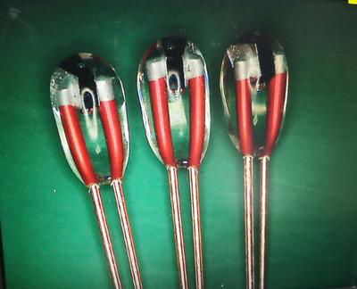
Glass Encapsulated NTC Thermistors
A sealed glass bubble protects encapsulated NTC thermistors. Using these thermistors, moisture penetration does not cause reading errors in resistance. Extreme temperatures & harsh environmental conditions do not affect these thermistors. They are designed for use at temperatures above 150°C. Glass encapsulation enhances the stability of a thermometer and protects it from the outside environment. The diameter of these thermostats typically ranges from 0.4 to 10 mm.
Advantages
These are some of the advantages of an NTC thermistor.
- They are highly flexible and sensitive.
- As a temperature sensor, it can detect temperature.
- The thermistors offer high accuracy and interchangeability at the same time.
- NTC thermistors are reliable, accurate, perform well, and have good heat resistance.
- Various sizes and tolerances are available.
- The main advantage of NTC thermistors over other temperature-sensitive resistors is their sensitivity.
- Temperature changes of even mild magnitude can trigger these thermistors.
- Their ability to detect a wave below one degree within a temperature range is excellent.
Disadvantages
There are several disadvantages associated with NTC thermistors.
- Since NTC thermistors are extremely sensitive components, they can damage entire appliances once they overheat.
- In the event of a damaged thermistor, the dryer will not function at all.
- Replacement is not possible since these are specially made.
- Choosing an NTC thermistor requires verifying the center temperature working point.
Applications
NTC thermistors are used in the following applications.
- NTC thermistors are used for measuring extremely low temperatures.
- These are normally used in current digital thermostats.
- When the battery is being charged, these are very useful for monitoring the battery’s temperature.
- Electronic circuits use these thermistors to limit current flow.
- They can also be used in place of fuses.
- Temperature compensation is achieved by using NTC thermistors.
FAQs
- What is the difference between NTC and PTC?
Positive temperature coefficient (PTC) thermistors have a resistance that increases as temperature increases, while negative temperature coefficient (NTC) thermistors have a resistance that decreases with temperature.
- What is the best way to choose an NTC thermistor?
When Choosing an NTC Thermistor, consider the following factors:
- Temperature Range
- Accuracy.
- Stability.
- Packaging.
- Immunity to noise.
- Is there a voltage range for NTC?
There is a range of output voltage between 71 millivolts and 3.231 volts.
Conclusion
In this article, we provided you with important information about NTC thermistors. We tried to give you a general overview of NTC thermistors, their principles, equations, specifications, applications, advantages, and disadvantages. For questions about choosing the right thermistor, contact Linquip Experts. You can also access a variety of Thermistors Service Providers via the Linquip platform if you need services related to your equipment.
Download PDF for What is NTC Thermistor?
You can download the PDF format of this post from the link provided here.
Buy Equipment or Ask for a Service
By using Linquip RFQ Service, you can expect to receive quotations from various suppliers across multiple industries and regions.
Click Here to Request a Quotation From Suppliers and Service Providers
Read More on Linquip
- What is a Thermistor and How its Working?
- Types of Thermistor; A Fundamental Comparison Between Them
- Thermistor Resistance: How does it Calculate?
- Thermistor vs Thermocouple: Complete Comparison & Practical Selection Guide
- Difference Between Thermistor and Thermostat: Which One Outperforms the Other?
- What is the Core Difference between Thermistor and RTD?
- What is PTC Thermistor? (Applications & Advantages)

