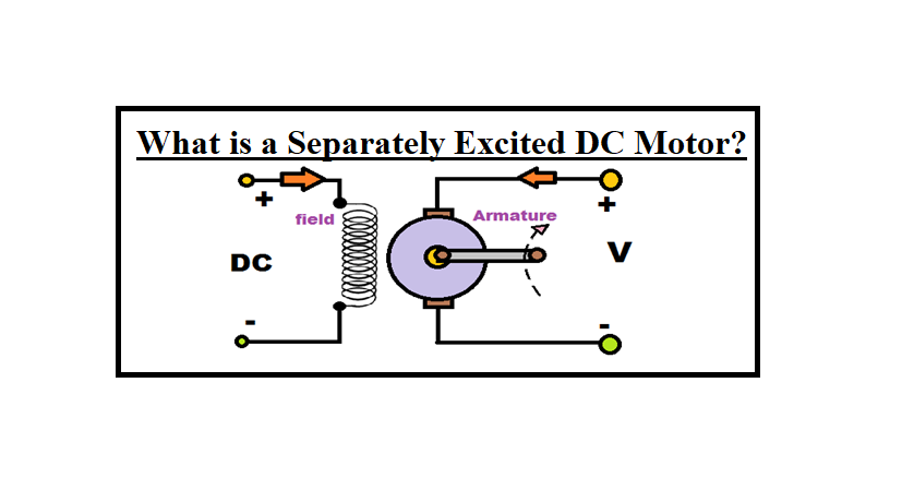
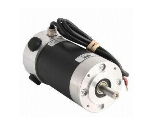
What is a Separately Excited DC Motor? Like other motors, these devices also have both rotors and stators. Stator refers to the static section of the device, which contains the field windings. The rotor is the rotating armature which consists of armature coils or windings. A separately excited DC motor includes some field coils similar to that of shunt-wound type. The name shows the structure of this type of motor. Typically, in other DC motors, the armature coil and the field coil are both powered from a single source. The field of them does not require any separate excitation. However, in a separately excited DC motor, a separate supply is used to excitation both the armature coil and the field coil.
These motors, like other DC motors, feature both a stator and a rotor. The field windings make up the stator, which is the static element of the motor. The rotor, on the other hand, is the moving armature, which is made up of armature windings or coils. The field coils of a separately stimulated dc motor are comparable to those of a shunt wound dc motor. The name alludes to how this sort of engine is built.
Separately excited DC motors are available from a variety of Suppliers and Companies, as well as various manufacturers and distributors, and there are several Separately Excited DC Motors for Sale on Linquip. There is a complete list of Separately excited DC motor services on the Linquip platform that covers all OEM fleets. Please call Separately Excited DC Motor Experts in Linquip to learn more about how to connect with a diverse group of Service Providers who consistently deliver high-quality products.
⇒ View a List of DC Motors for Sale and Their Suppliers ⇐
What is a Separately Excited DC Motor?
As the name presents, in the case of a separately excited DC motor, the main supply is given separately to the armature and field windings. The major distinguishing fact in these forms of DC motor is that the armature current does not move across the field windings as the field winding is powered from a separate external supply of DC. From the torque equation of motors, we know that:
T_{g} = {K}_{a} \phi {I}_{a}
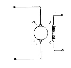
So, the torque, in this case, can be changed by modifying the field flux (φ), independent of the current of the armature (Ia). The figure below presents the separately excited DC motor.
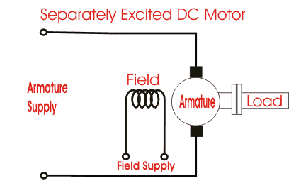
Here, the field coil is powered from a separate DC voltage supply, and the armature coil is also powered from another source. Armature voltage supply may be variable but, an independent fixed DC voltage is applied to induce the field coil. Therefore, those coils are electrically separated from each other, and this junction is the main feature of this type of motors.
Definition of a Separately Excited DC Motor
Direct current motors have been using to provide the field of adjustable speed controllers for over a century; they are still the most applicable option if a controlled electrical drive working over a wide velocity level is specified.
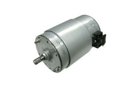
This is because of their excellent performance features and control properties; the only essential drawback is the mechanical commutator which reduces the speed and power of the motor, maximizes the inertia and the axial length, and needs too periodic maintenance than the other types. The commutator is removed with alternating current motors, supplied by variable frequency static power converters, but the cost can be increased because of their complexity.
This is one of the main reasons why new AC controllers could not quickly supplant DC types, once the semiconductor technology had significantly improved.
The principle of a DC motor performing in steady-state is assumed to be known, but let us discuss some basic facts below.
Working Principle of a Separately Excited DC Motor
A schematic cross-section across a two-pole DC motor is presented in the next figure, including the fixed stator S and the cylindrical rotor, introduced as armature A. Once rotor and pole shoes are always connected in order to decrease the iron wastes caused by the varying magnetic flux, the rest of the stator is laminated just in huge machines, when the device is needed to perform with fast varying torque and speed or once a static power converter with greatly distorted currents and voltages is used as the power supply.
The basic poles (M and P) are connected with the field windings, moving the field current ie which runs the main flux across the rotor and stator. A closed armature coil is set in the axial slots of the rotor and combined with the commutator bars; it is provided by the brushes and the commutator produces the armature current ia. This generates a distributed ampere-turn (mmf) wave, fixed in the space and rotated in the direction of the quadrature axis, orthogonal to the basic axis, so that maximum output torque for the armature current can be created.
In the case of the great distance in the quadrature direction, the resulting armature flux is much smaller than the basic flux. It can be decreased even further by setting compensating coils in the axial slots on the pole shoes and arranging them in series with the armature. Their opposing ampere-turn stops the quadrature field induced by the armature and eliminates the undesired armature reaction, which otherwise wants to distort the even distribution of the main flux under the poles across the circumference of the rotor.
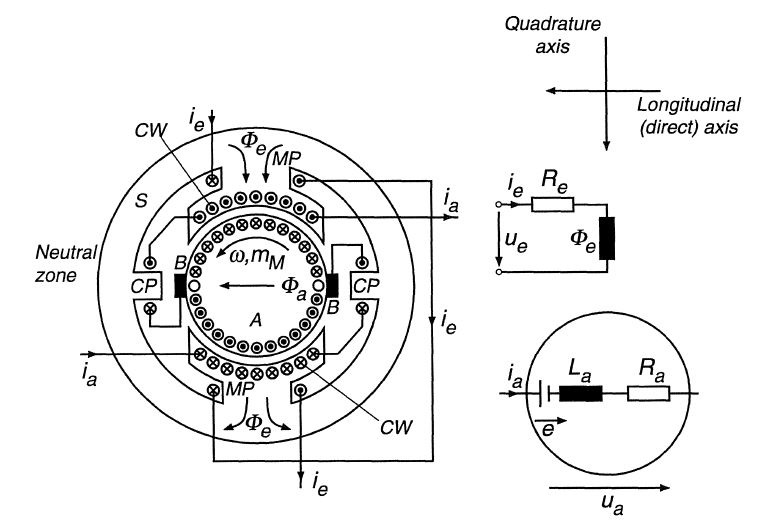
Compensating coils are popular only on huge machines or converter-fed devices for heavy-duty cases such as steel-mill or traction drives. Compensated DC motors can tolerate higher overloads than uncompensated forms. The armature current may increase much quicker and greater current harmonics are acceptable without detrimental influences on the commutation, i.e. sparking of brushes. This is too important if the motor is supported by a static converter.
The commutating poles (C and P), installed between the main poles and also carrying the armature current, have the main task of locally varying the field in the neutral place, in order to obtain rapid and spark-free commutation. This is performed by producing an appropriate voltage in the armature coil temporarily reduced by the brushes.
The principle of commutation is very simple, where the closed armature section of a two-pole DC motor is generally performed, providing the brush positions at two consecutive instants of time. Generally, when the feeding points of the winding are switched by the relative movement of the brushes to the next commutator bars, the commutating winding is immediately short-circuited, whereas the current is inverted.
Because each winding, being embedded in slots covered by iron, presents some inductance, the commutation is a constant process that takes a finite time; this restricts the speed at which the device can perform without excessively sparking brushes. Visit here
What Is the Advantage of Separately Excited Dc Motor?
Compared to self-excited DC generators, separately excited DC generators have a number of benefits. It has a broad range of output voltage and can function in stable conditions with any field excitation. The primary downside of these generators is that having a separate excitation source is quite costly.
Equations of Voltage, Current, and Power for a Separately Excited DC Motor
In a separately excited DC motor, field and armature windings are excited to form two various DC supply voltages. In this motor, we have
- Armature current Ia = Line current = IL = I
- Back emf developed:
E_{v} = V-I{R}_{a}
where V is the main voltage and Ra is the armature resistance.
- Power is drawn from the main source:
P=VI
- Mechanical power developed (Pm) = Power input to the armature – power wasted in the armature
Operating Characteristics of a Separately Excited DC Motor
Both in shunt-wound and separately excited types, the field is supported from a regulated voltage, so that the field current is fixed. Thus, these two motors have identical speed-armature current and torque–armature current features. In a separately excited DC motor, the flux is assumed to be constant.
Speed – Armature Current (N – Ia) Characteristics
We know that the speed of a motor is related to the back EMF/flux i.e. Eb / φ. Once the load is increased, back EMF and flux reduce because of the armature resistance reduction and armature reaction respectively. However, back EMF reduces more than flux, so that the speed of the motor slightly drops with the load.
Torque – Armature Current (Τ – Ia) Characteristics
Here torque is related to the flux and armature current. Regardless of the armature reaction, flux is fixed and torque is related to the armature current Ia. T– Ia feature is a straight line passing across the origin. From the curve, we can understand that a large current is required to start heavy loads. So, this form of motor does not start on heavy loads.
Speed Control of a Separately Excited DC Motor
The speed of this type of DC motor is determined by the following methods:
- Field control: Reduction of the field increases the speed of the device while improving the field causes reduction in the speed. Speed regulation of this type of motor can be obtained by controlling the field. Field voltage control is applied by changing the voltage at the field circuit while keeping armature terminal voltage fixed.
- Field rheostat control: Here a variable resistance is arranged in series form with the field coil. Therefore, the speed is determined by means of flux variation. Reluctance control is also used by variation of the reluctance of the magnetic circuit of the device.
- Armature control methods: Speed regulation of a separately excited DC motor by armature control may be achieved by any one of the following methods: a) Armature resistance control (Here, the speed is determined by changing the source voltage to an armature. Typically, a variable resistance is used in the armature to change the armature resistance), b) Armature terminal voltage control that is used to change the voltage in the armature circuit.
Speed-Torque Characteristic of a Separately Excited DC Motor
The main formulation of a speed-torque Characteristic of a separately excited DC motor whose armature, including a total of Z conductors, is wound for 2P poles (the brushes separate the winding into 2 parallel paths), is
{V}_{a} = E+{I}_{a}{r}_{a}
Where E is the back emf of the armature obtained by
E=\frac{\phi ZN}{60}\frac{2P}{2a}={K}_{e}\phi N={K}_{t}\phi \omega
where ω is the angular speed introduced as
\omega=\frac{2\pi N}{60}
and Ke and Kt are constants.
From the above equation, we get
N=\frac{{V}_{a}-{I}_{a}{r}_{a}}{{K}_{e}\phi }
The torque produced by the device is given by
{T}_{d}=\frac{1}{2\pi }2P \phi \frac{{I}_{a}}{2a}Z={K}_{t}\phi {I}_{a}
Substituting for Ia in the last formula, we have
N=\frac{{V}_{a}}{{K}_{e}\phi }-\frac{{T}_{d}}{{K}_{t}{K}_{e}{\phi }^{2}} {r}_{a}
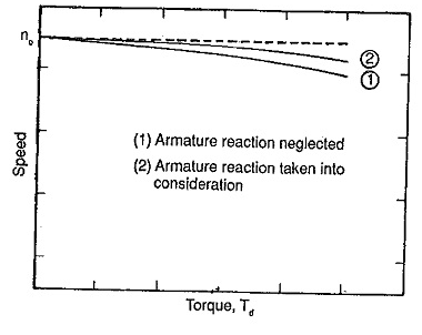
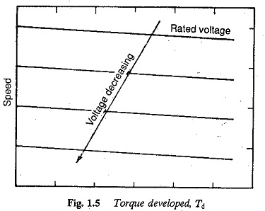
Once Td is zero, the corresponding speed N0 is the no-load condition. The motor speed reduces as the torque increases causing a drooping characteristic. The speed-torque diagrams are presented below. These diagrams clearly demonstrate a speed reduction of 2 to 3% as the torque changes from no-load to full load.
In DC motors, the armature MMF reacts to the field MMF. This behavior is introduced as the armature reaction. Once the effects of the armature reaction are removed, the flux per pole of the device is constant and is independent of power.
In standard construction, the brushes are located in the neutral zone. The armature reaction, though cross magnetizing, can be resumed by demagnetization because of the saturation. The effect of demagnetization on the field because of the armature flux is too obvious and shown in the figure below. The speed reduction from no-load to full load reduces, improving speed control.
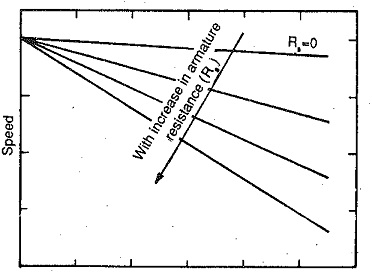
The effect of external resistance in the armature circuit is presented in the figure below. Speeds in the level of zero to main speed may be achieved. With an appropriate amount of R, very slow speeds are feasible at the cost of efficiency.
The speed-torque diagrams for a smooth change of the armature voltage are presented below. They move along the Y-axis (velocity axis) following variations in the armature voltage. The field winding of the device is supported by a separate supply.
The smooth change of the armature voltage brings about speed adjustment in the zero to base speed level very efficiently. The device performs in a fixed torque mode. This method of sensing the speed of a separately excited DC motor employing variable voltage to the armature is used in different applications to control the amount of speed.
The effect of the field current change on the speed-torque feature is another method used for speed control. The field current is reduced to obtain speeds above the main speed when the armature voltage obtains its rated amount.
The flux weakening mode is the best approach for constant power cases as the armature current may be maintained at its curtained amount. The torque also reduces in this mode. In the flux weakening method, the device cannot be utilized to drive fixed torque loads as the motor draws raised currents as the speed improves. This method is applied to achieve speeds in the range of base value to twice base one. The largest speed accessible by the flux weakening is restricted by commutation.
The armature current can remain fixed in a full range of speeds from zero to twice base speed. The method used in this mode is feasible with shunt motors also through a variable amount of resistance in the field circuit.
Applications of Separately Excited DC Motor
A separately excited DC motor has industrial applications. It is typically used as an actuator. This form of motors is employed in trains and for automatic traction aims.
Download separately excited dc motor PDF
Buy Equipment or Ask for a Service
By using Linquip RFQ Service, you can expect to receive quotations from various suppliers across multiple industries and regions.
Click Here to Request a Quotation From Suppliers and Service Providers
Read More In Linquip
- Working Principle Of DC Motor: 2022 Complete Guide
- DC Motor Efficiency: Calculation: Formula & Equation
- What is a Series Wound DC Motor?
- DC Motors vs Servo Motors: A Complete Comparison
- Separately Excited DC Motor
- The Difference Between DC Motor and Stepper Motor: Everything You Need To Know
- Universal Motor: a Simple Guide to Construction, Types and Working
- What are the Advantages of DC over AC?
- A complete Guide to The Difference Between Stepper Motor and DC Motor
- DC Motor Working Principles : The Most Compendious Reference
- Compound DC Motors: Everything You Should Know About DC Compound Motors
- 4 Different DC Motor Types and Their Applications
- Shunt DC Motors: An Easy-to-Understand Explanation of Working Principle and Components
- Brushed DC Motor: A Comprehensive Explanation of Working Principle, Parts, and Types
- All About DC Motor Types and Their Applications
- Shunt DC Motors: An Easy-to-Understand Explanation of Working Principle and Components
- Series Wound DC Motor

