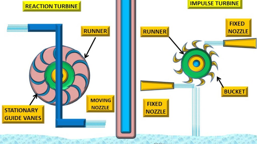
The difference between impulse and reaction turbine is generally how potential form of energy is converted to rotate the turbine wheel. A working fluid holds potential energy as a pressure head and kinetic energy as a velocity head. The fluid may be whether compressible or incompressible. Impulse and reaction turbines employ different physical principles to use this energy.
The primary distinction between an impulse and a response turbine is that in an impulse turbine, steam passes via the nozzle, but in a reaction turbine, steam passes through the guiding mechanism before passing through the rotating blades. In the industrial tools category, impulse and reaction turbines are essential. There are several Impulse and Reaction Turbines for Sale on Linquip from a range of vendors and firms, as well as various Manufacturers and Distributors.
A full list of impulse and reaction turbine services is available on the Linquip website, which covers all OEM fleets. Linquip vendors can assist you with this. Please contact Linquip’s Impulse and Reaction Turbine Experts to learn more about how to connect with a wide choice of service providers who consistently deliver the highest quality products.
Difference between Impulse and Reaction Turbine
In this section, we will mention items to describe the difference between impulse and reaction turbine.
From the Perspective of the Physical Principles of Operation
Turbines operate in two distinct ways which are described as impulse and reaction.
Impulse Turbine
Impulse turbines change the direction of fluid flow or gas jet at high velocities. The resulting impulse rotates the turbine, the kinetic energy of fluid flow reduces, and then it leaves the turbine. In the turbine moving blades, there is no pressure change of the fluid (liquid or gas).
In a steam or gas turbine, all the pressure reduction occurs in the stationary blades (the nozzles). Before reaching the turbine, the change in pressure head of the fluid to velocity head takes place by accelerating the fluid with a nozzle. In the case of Pelton wheels and de Laval turbines apply this process thoroughly.
Impulse turbines do not need a pressure chamber around the rotor because the nozzle generates the fluid jet before it reaches the rotor blades. Newton’s second law describes the energy transfer in impulse turbines. Impulse turbines are most efficient for use with low flow and high inlet pressure.
Reaction Turbine
Reaction turbines generate torque by reacting to the pressure or mass of the gas or fluid. The gas or fluid pressure changes passing through the turbine rotor blades. The casing holds and guides the working fluid and, for hydraulic turbines, maintains the suction transmitted by the draft tube. Francis turbines and most steam turbines work with this idea.
For compressible working fluids, several stages of the turbine are often used to control the expanding gas effectively. Newton’s third law explains the energy transfer for reaction turbines. Reaction turbines are better fitted to higher flow rates or cases where the upstream fluid head (pressure) is low.
What Is Steam Turbine Differentiate Between Impulse and Reaction Turbine?
Steam impacts the spinning blades with kinetic energy exclusively in an impulse turbine. In a reaction turbine, however, the steam that passes over the rotating blades has both pressure and kinetic energy. During the passage of steam through the rotating blades of an impulse turbine, the pressure of the steam remains constant.
Which Is More Efficient Impulse or Reaction Turbine?
In comparison to the impulse turbine, the response turbine has more blades. As the steam passes through the rotor blades, they rotate. The steam in a reaction turbine travels in the same direction.
From the Perspective of Applications
Depending on the type of fluid and the industrial application of the turbine and also the fluid flow conditions, impulse or reaction turbines can be manufactured and presented in different types.
Impulse Turbine
Impulse turbines are used in all types of gas, water, and steam turbines.
Impulse Gas Turbine
The impulse turbine comprises a row of nozzles and then a row of blades. The gas is expanded in the nozzle and converts the high heat energy into kinetic energy, represented by the following equation:
V=\sqrt{2\Delta V}
The high-velocity gas strikes the blade. A large part of the kinetic energy of the flowing gas is converted into turbine shaft mechanical work. A schematic diagram of a single-stage impulse turbine is shown in the following figure:
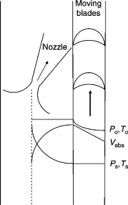
The static pressure in the nozzle decreases with an increase in the absolute velocity. The absolute velocity in the rotor then decreases, but the relative velocity and the static pressure remain constant. All enthalpy drop occurs in the nozzle, and the nozzle outlet velocity is much high. As the enthalpy in the rotor does not change, the relative velocity entering the rotor is equal to the relative velocity leaving the rotor blade.
Impulse Water Turbine
The impulse hydraulic turbine uses the impulse or kinetic energy in a flow of water to run the turbine and generate power. An impulse turbine uses a strong jet of water that is produced from a high head of water.
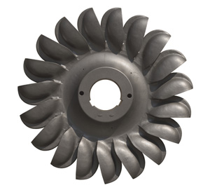
The basis of impulse turbine work is as follows:
A tall column of water produces a lot of pressure at its base due to the mass of the water pushing down on it. If the water under high pressure is delivered through a proper nozzle, it generates a high-speed jet of water. If this jet is guided to bucket-shaped blades mounted on the circumference of a wheel, it will cause an impulse that will lead the wheel to rotate.
The power available for the water turbine is as the following relation. It depends on the efficiency of the turbine that how much of the power can be converted to output power as electricity.
P=\rho gQh
In the above equation, Q and h are water mass flow and net head upstream of the turbine.
One of the most common impulse turbines in use is the Pelton turbine, first patented by Lester Allan Pelton in 1889. It operates by shooting a jet of water at buckets mounted around a wheel. The Pelton turbine works at its highest efficiency, up to 95%.
As shown in the figure below, a modern Pelton turbine is equipped with a set of spoon-shaped buckets installed on the circumference of a wheel. The buckets are meticulously arranged in a way that the water from the jet striking the bucket changes its direction and leaves at the opposite side. So, the water transfers its momentum to the turbine runner. In this process, the water gives most of its momentum to the runner and exits the bucket in the changed direction.
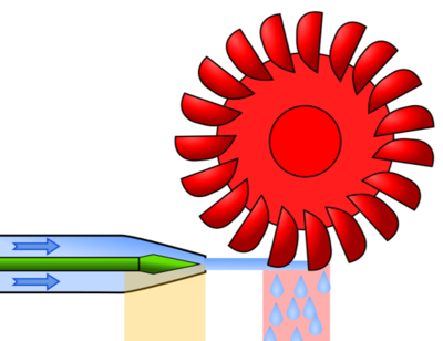
Sometimes, the Pelton turbine has two rows of buckets around the circumference, driven by two jets. This improves balancing the lateral forces on the runner and helps smooth operation.
The Pelton turbine is used for the sites with a high head of water and a relatively low flow rate. In large hydropower plants, they are usually used for heads more than 450 meters. However, they can be applied for heads as low as 200 m. The maximum head for a single Pelton unit is about 1000 meters.
A simple Pelton turbine has one or two jets or nozzles, but the output power can be increased by employing up to four nozzles guided at the same runner. One of the main features of all Pelton turbines is that they have to work in free air, with no submerged component. Submerged parts cause drag on the runner and energy waste.
The speed at which a Pelton turbine spins is determined by both the flow rate of water led to the buckets and the required load. If the load falls, the turbine speeds up. So it needs to be controlled by reducing flow via the nozzles. The largest Pelton turbines can generate powers up to 400 MW, while the smallest Pelton turbines are able to generate 5 kW or less.
Another type of impulse turbine used for high head applications is the Turgo turbine. It is similar to the Pelton in design, but with a significant difference: the water jets are in the same plane as the Pelton runner, but in the Turgo turbine, the jet hits buckets at a diagonal angle. The Turgo turbine is generally more challenging to construct. Turgo turbines are commonly used for medium-head sites between those suitable for the Pelton and those suitable for reaction turbines.
To know more about the Turgo turbine, visit here.
Impulse Steam Turbine
In a steam turbine, the inlet and outlet pressures and the inlet temperature of the steam determine the energy obtainable at the turbine inlet. An impulse steam turbine consists of a stage of stationary nozzles followed by a stage of rotating blades. In nozzles, the potential energy of steam is transformed into kinetic energy.
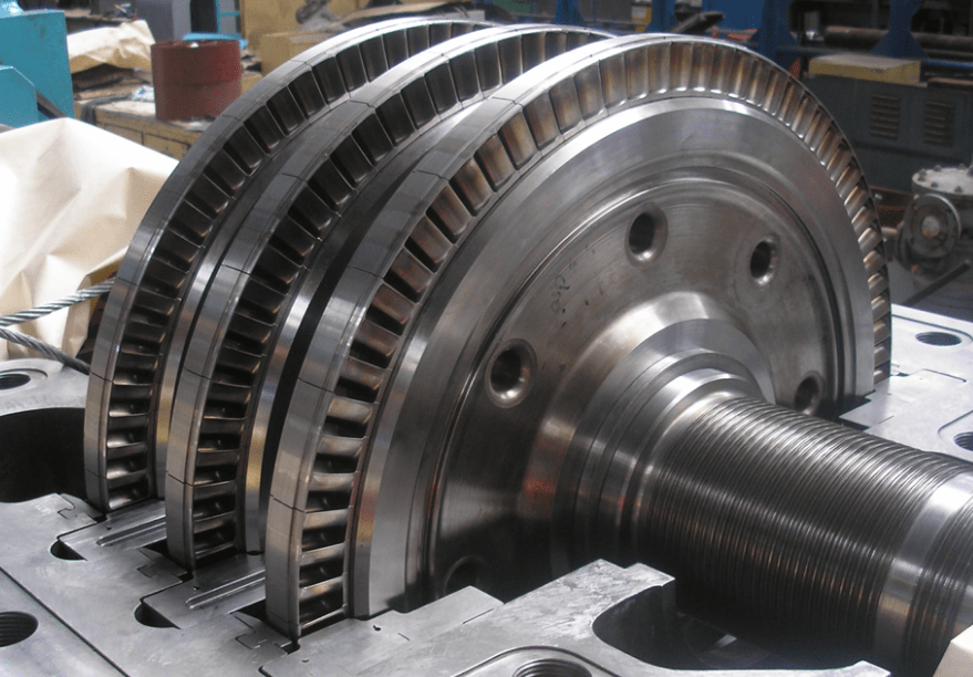
A complete steam expansion process with a resulting pressure drop happens only across these nozzles, with a net rise in steam velocity over the stage. The moving rotor blades receive the kinetic energy of high-velocity steam jets and turn it to mechanical work in the form of rotation of the turbine shaft. No heat drop and no pressure drop occur in the moving blades. Therefore, the moving blades mechanical work is simply due to the loss of a proportion of the velocity obtained in the fixed blades.
When a stream jet strikes on a frictionless curved blade, the resulting velocity diagram can be drawn as shown in the following figure:
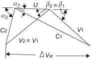
The available energy to the stage of rotor blades of an impulse turbine is (C1 is the absolute steam velocity at entering the blade):
E=\frac{mC_{1}^{2}}{2g}
It can be proved that the maximum efficiency of a steam impulse turbine depends entirely on the steam entrance angle and is calculated as follows:
\eta _{max}=cos^2{\alpha _{1}}
Reaction Turbine
Like impulse turbines, reaction turbines are used in a variety of gas, water, and steam turbines.
Reaction Gas Turbine
The axial-flow reaction turbine is the most broadly used gas turbine. In a reaction turbine, the nozzles and blades both work as expanding nozzles. Therefore, the static pressure reduces across both the fixed and moving blades. The fixed blades perform as nozzles and guide the flow to the moving blades at a velocity somewhat higher than the moving blade velocity. The velocities in the reaction turbine are often much lower, and the entering blade relative velocities are almost axial.
The following figure demonstrates the axial reaction gas turbine schematically:
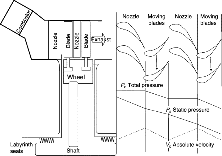
The work provided by a reaction turbine is half of that of a single-stage impulse turbine running at the same blade speed. Therefore, the cost of a reaction turbine for the same generated work is much higher because it needs more stages.
To maximize the work, usually, multistage turbines including impulse stages in the first few stages followed by reaction turbines are used. The efficiency of the reaction turbine is higher due to blade suction effects. This combined construction has the advantage that both the number of stages is less than a fully reaction turbine, and the efficiency is higher than a fully impulse turbine.
Reaction Water Turbine
Reaction turbines usually are the first choice for hydraulic heads below 450 m. This type of turbine must be entirely submerged to run efficiently. While the impulse turbine gets the kinetic energy and the momentum transferred by the water mass of a high-pressure jet, a reaction turbine is subjected to the pressure or potential energy generated by the weight of water at the bottom of the head working on one side of its blades called pressure side.
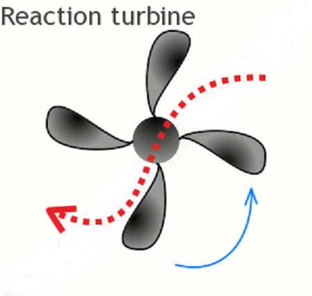
There are several types of reaction turbines. The most common, which accounts for 80% of all hydraulic plants in operation, is the Francis turbine. They operate in a wide range of heads between 10 to 650 meters. They are classified in radial and mixed classes as inward-flow reaction turbines. So, Francis can be installed in almost every flow condition. However, for very low heads, propeller turbines (for heads of 1.5 to 15 meters) and Kaplan turbines (for heads of 10 to 70 meters) are usually preferred.
In reaction turbines, only a portion of the overall pressure drop occurs before the turbine entry, and the remaining pressure drop happens in the turbine. Unlike the Pelton turbine in which for each jet, only one or two of the buckets are in contact with the water at a time, the flow fills all of the runner passages in a reaction turbine. Also, a row of guide vanes is applied to control and direct the flow to the runner. Furthermore, a draft tube is installed in the turbine exit, which is considered an important turbine component.
Reaction Steam Turbine
A reaction turbine is built up of rows of fixed blades (as nozzles) and moving blades. The motion of moving blades is a result of the impulse of steam (caused by a momentum change) as well as the steam expansion and acceleration relative to them. In other words, they act also like nozzles.
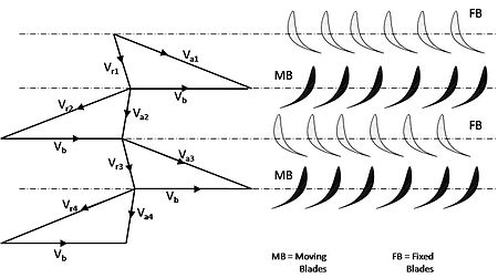
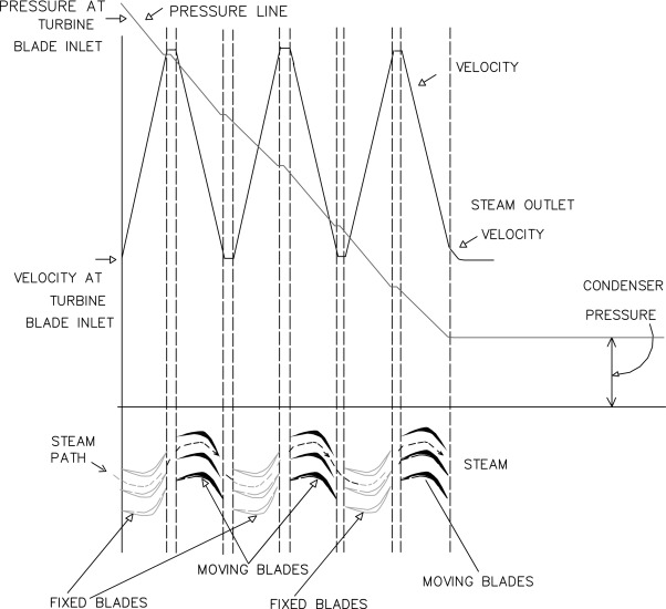
The pressure drop in each stage is distributed across the fixed and moving blades in the reaction turbine. The fixed blades accelerate the steam to a medium velocity due to the partial pressure reduction. The steam then strikes on the moving blades and gives some energy to them.
Across the moving blades, the steam is accelerated by the remains of the pressure drop. This acceleration causes a reaction effect and delivers more energy to the moving blades. The steam exits the stage at a low velocity relative to the following row of fixed blades.
From the Perspective of How Energy Is Exchanged
Impulse and reaction turbines vary depending on the type of energy the flow to which the turbine is exposed to.
Impulse turbine
The fluid stream fed to the moving blades of the impulse turbine has only kinetic energy.
Reaction turbine
The flow within the reaction turbine holds both pressure and kinetic energy throughout the moving blades.
From the Perspective of Blades Shape
The difference between the forms of blades is as follows:
Impulse Turbine
The shape of the turbine blades is usually symmetrical.
Reaction Turbine
In reaction turbines, the structure of blades is not usually symmetrical.
From the Perspective of Relative Velocity Changes
The following explanation can be given about how relative velocity changes.
Impulse Turbine
In an impulse turbine, the relative velocity of flow remains constant.
Reaction Turbine
The relative velocity in the Reaction turbine increases when it slides on the blades.
From the Perspective of the Flow Direction inside the Turbine
The direction of fluid through the turbine can be varied depending on the application.
Impulse Turbine
The flow in most gas turbines is axial. The flow in Impulse water turbines is generally tangential to the blades. Steam turbines also have radial flow.
Reaction Turbine
The flow in reaction turbines is both radial and axial.
From the Perspective of Maintenance Works
Depending on the working conditions and the turbine building, the necessary works for maintenance and repair can vary. Impulse turbines need less maintenance than reaction turbines.
Impulse-Reaction Turbines
Modern turbine designs apply both reaction and impulse ideas whenever possible. Wind turbines use an airfoil to produce a reaction lift from the moving fluid and transfer it to the rotor. Wind turbines also obtain some energy from the impulse of the wind by turning it at an angle. Multiple-stage turbines may use either reaction or impulse blades at high pressure.
Steam turbines have traditionally been of impulse type but move towards reaction designs like those utilized in gas turbines. At low pressure, the working fluid medium expands for small reductions in pressure.
Under these conditions, most of the blade style becomes reaction type design with only the base of the impulse blade. This is because of the effect of the rotational speed for all blades. As the volume rises, the height of the blade increases and the blade base spins at a slower speed relative to the tip. This change of speed forces the designer to move from impulsive design at the base to a high reaction style at the blade tip.
Download difference between impulse and reaction turbine PDF
Buy Equipment or Ask for a Service
By using Linquip RFQ Service, you can expect to receive quotations from various suppliers across multiple industries and regions.
Click Here to Request a Quotation From Suppliers and Service Providers
Read More on Linquip
- Impulse Turbine: Working Principle, Components, and Types
- Types of Turbines: Classifications and Types
- Differences between Pelton, Francis, and Kaplan Turbine
- The Ultimate Guide to The Difference Between Gas Turbine and Reciprocating Engine
- Quick Guide: The Difference Between Gas Turbine and Diesel Engine
- Best LED Fixtures for Warehouse and Garage of 2022
- Types of PVC pipes and their application
- Difference between Petrol and Diesel Engine: An Easy-To-Understand Comparison
- Important Detailed Information About The Types of Fossil Fuels
- The 10 Best System Boilers of 2022
- Types of Fossil Fuels: All You Should Know
- Everything You Need To Know About The Difference Between DC Motor and AC Motor

