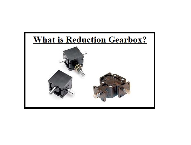
A reduction gearbox, or speed reducer, is used to decrease the velocity of the input from the motor while also improving the torque the input produces. The device is applied to transform the output shaft revolutions of the basic engine to those needed to move the propeller. The reduction gearbox contains the meshing teeth on wheels and pinions, which transfer the energy from a drive shaft to a driven shaft and decrease the speed.
There is a wealth of information on Linquip’s website regarding gearboxes, and we strive to supply you with as many details as possible to help you choose a product that will work well for your application. If you are looking for answers to any questions about reduction gearboxes, Linquip is the best option for you. Experts at Linquip are always available to answer any questions you may have about these devices or equipment. Please take a moment to read Linquip’s article titled, “What is Gearbox?” if you have not already done so.
In order to be able to take advantage of the Linquip platform to the fullest of its abilities and access the entire range of Linquip components, you will need to register as a Linquip Expert. Creating an account on Linquip will give you the opportunity to showcase your skills that are related to industrial technologies in a way that can be tailored to the needs of the industry. Are you willing to write a guest blog post for Linquip if you are interested in doing so? With Linquip’s Guest Posting feature, you can add content directly on the site.
What is a Reduction Gearbox?
The reduction gearbox, also introduced as a torque multiplier or speed reducer, is employed to decrease the output speed of the motor. Reduction gearboxes are too simple in construction, like a gear train between the motor and the machinery. The ratio of output to the input gear is such that it permits the output shaft to move more slowly, supplying the increased torque and reduced speed.
Some types of reduction gearboxes are operated as a gear train between different parts, but regardless of complexity, the reduction is feasible since the output section has more teeth than the input section allowing the output gear to move more slowly, decreasing the speed, and increasing torque. The input velocity can be monitored with a speed reducer so that the output is the correct torque and speed.
Therefore, choosing the right speed reducer is an essential aspect of using them. Finding the best speed reducer for the application is important to ensure the function. Here is a free checklist (the speed reducer buying checklist) that will guide you through the process of meeting your requirements with the information needed in your application to allow your supplier to turn it into reality.
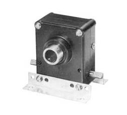
This guide will help you choose the reduction gearbox:
- Speed and duty cycle
- Applications specific details
- Input/output requirements
- Shock and loading influences on the service factor
- Housing details
Definition of a Reduction Gearbox
The reduction gearbox is a familiar term to many, but what does it really mean?
On the surface, it may seem that devices are being “reduced” in size or quantity, which is approximately true. Once a rotary device such as an engine or electric motor requires the output speed decreased and/or torque increased, gears are typically employed to accomplish the suitable result. Gear “reduction” particularly refers to the velocity of the rotary system; the rotational speed of the rotary instrument is “reduced” by separating it by a gear ratio higher than 1:1.
A gear ratio larger than 1:1 is obtained once a smaller gear (decreased size) with a smaller number of teeth meshes and runs a larger section with a greater number of teeth.
A reduction gear is a configuration by which an input velocity can be reduced for a requirement of slower output speed, with identical or more output torque. A reduction gearbox assembly includes a set of moving gears combined with wheel work. The high-speed incoming movement from the wheel function is transferred to the arrangement of rotating gears, wherein the torque or motion is changed. The number of gears used in the reduction gearbox is based on the output speed requirement of the case. The reduction gearbox is usually known as reduction gear assembly.
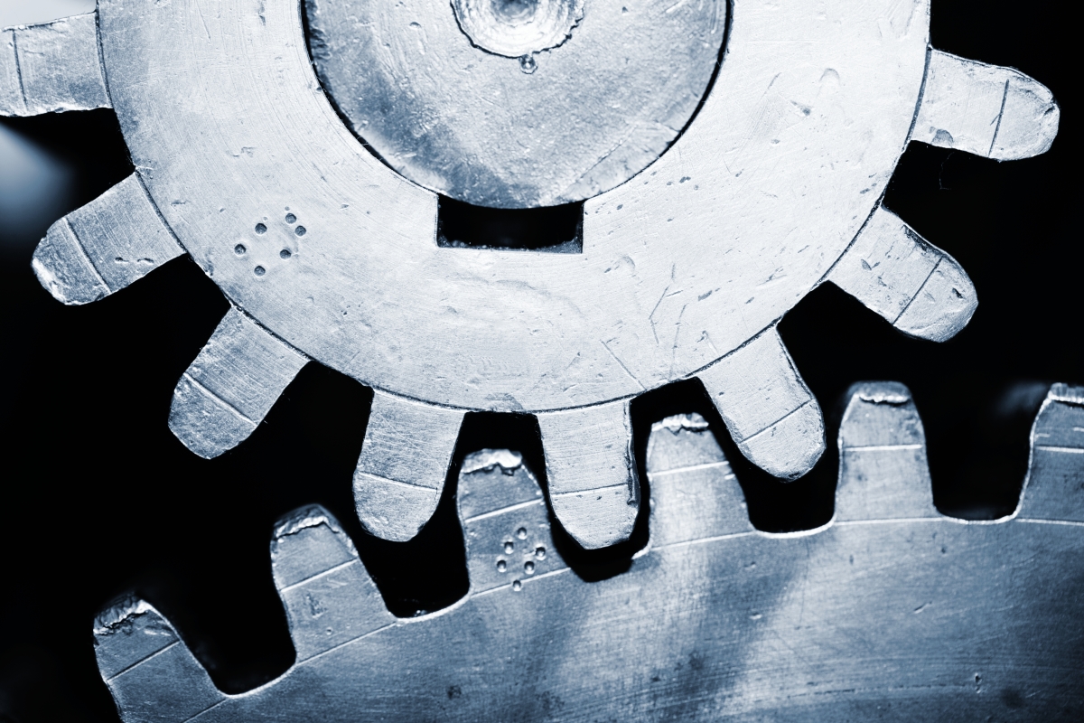
Gear reduction has the opposite impact on the torque. The rotary system’s output torque can be increased by improving the torque by the gear ratio, less some efficiency wastes.
Whereas in many cases, gear reduction decreases speed and increases torque, in other applications, gear reduction is applied to develop speed and decrease torque. Generators in wind turbines apply gear reduction, in this case, to transform a comparatively slow turbine blade velocity to a great speed capable of producing electricity. These applications employ a reduction gearbox that is assembled opposite of those in cases that control speed and increase torque.
How a gear reduction is achieved is another main question. Many reducer forms are able to attain gear reduction including, but not restricted to, parallel shaft, right-angle, and planetary worm gearboxes. In a parallel shaft reduction gearbox (or reducer), a pinion gear with a particular number of teeth meshes is used and runs another gear with a higher number of teeth.
The “reduction” or gear ratio is evaluated by dividing the number of teeth on the great section by the number of teeth on the small side. For instance, if an electric device drives a 13-tooth pinion gear that meshes with a 65-tooth section, a reduction of 5:1 is obtained (65 / 13 = 5). If the electric device’s speed is 3,450 rpm, the reduction gearbox decreases this velocity by five times to 690 rpm. If the device torque is 10 lb-in, the gearbox improves this torque by a coefficient of five to 50 lb-in (before subtracting out the device efficiency wastes).
Why is a Reduction Gearbox Used?
To know why a reduction gearbox is used in a particular system, we will take an instance of a ship employing high-speed turbines. It is the main requirement of a ship that in order to have suitable efficiency, the steam turbine must perform at a comparatively high range of rpm although the effective operation of a propeller needs a relatively low rpm state. For this reason, a reduction gearbox is applied, which decreases the high-speed rotation of the steam turbine into the low rpm level needed by the propeller. Visit here to see the different applications of a reduction gearbox.
Types of Reduction Gearbox
There are generally two types of reduction gearboxes:
- Single Reduction Gearbox
- Double Reduction Gearbox
Single Reduction Gearbox
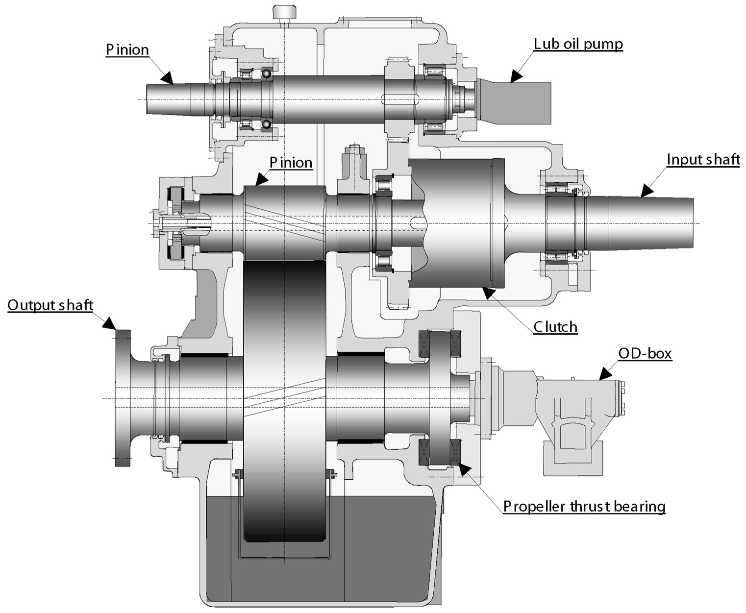
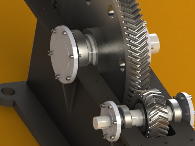
This assembly contains only one pair of gears. The reduction gearbox includes ports across which the engine shaft and propeller shaft enters the assembly. A small gear defined as a pinion is performed by the incoming engine shaft. The pinion directly runs a great gear connected to the propeller shaft. The speed is regulated by making the ratio of the speed adjustment to the diameter of gear and pinion proportional. In general, a single gear arrangement includes a gear double the size of the pinion.
Double Reduction Gearbox
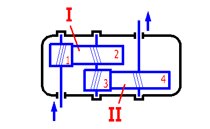
Double reduction gearboxes are commonly used in cases involving very high speeds. In this assembly, the pinion is mounted on the input shaft employing a flexible coupling. The pinion is joined to an intermediate section defined as the first reduction gear. The first reduction gear is then attached to a low-velocity pinion using one more shaft. This pinion is mounted to the second reduction section connected directly to the propeller shaft. Such assembly facilitates the decrease of speed to a ratio as large as 20:1.
Other types of reduction gearbox are available in the market to use in particular applications. Some of them are:
Magnetic Reduction Gearbox
Magnetic gear reducers or magnetic reduction gearboxes can advantageously replace the typical gear reducers to guarantee the torque and speed control by applying the magnetic attraction instead of physical touching between moving components. To date, complex arrangements, low torque, and high weight have slowed the diffusion of this magnetic process.
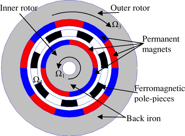
Magnetic gears remove the requirement for lubrication and therefore reduce the maintenance prices. No need for lubrication also means that devices can perform at extreme temperatures (currently used from -200˚C to 350˚C).
These benefits are particularly significant for cases with high maintenance costs or for those operating in extreme conditions such as satellites and other aerospace instruments.
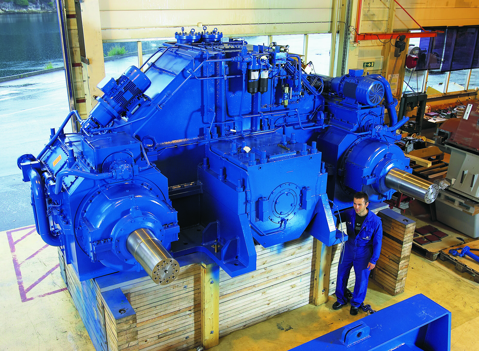
Along with corrosion and usage, wear is one of the three major factors restricting the life and function of mechanical parts and technical devices. With a magnetic reduction gearbox, the absence of friction not only removes the wear of the device but also has a considerable effect on the service life, which can be the key to use systems continuously that cannot be simply replaced.
Material detached from the worn plane in traditional transmissions cannot be simply eliminated, which can be a considerable cause of contamination. Contamination is a significantly serious drawback for instruments that cannot be constantly maintained.
Parallel Shaft Reduction Gearbox
The parallel shaft reduction gearbox many times includes multiple gear arrangements thereby increasing the system reduction. The whole gear reduction ratio is specified by improving each individual gear ratio from each gear section. If a gearbox includes 5:1, 4:1, and 3:1 sections, the total ratio is 60:1 (5 x 4 x 3 = 60). In our case above, the 3,450 rpm electric device would have its speed decreased to 57.5 rpm by applying a 60:1 gearbox. The 10 lb-in electric device torque would be raised to 600 lb-in (before efficiency wastes).
If a pinion gear and its mounting part have an identical number of teeth, no reduction happens and the gear ratio is 1:1. The gear is introduced as an idler and its primary performance is to vary the rotation direction rather than reduce the speed or increase the torque.
Planetary Reduction Gearbox
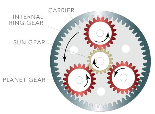
Evaluating the gear ratio in a planetary reduction gearbox is less intuitive as it is dependent on the number of teeth of the ring gears and sun ring gears. The planet gears perform as idlers and do not influence the gear ratio. The planetary gear ratio is the same as the sum of the number of teeth on the ring and sun divided by the sun gear teeth number. For instance, a planetary arrangement with a 15-tooth sun gear and a 90-tooth ring gear has a ratio of 7:1 ([15 + 90]/15 = 7). Planetary gear arrangements can obtain ratios between 3:1 to 11:1. If more reduction ratio is required, additional planetary stages can be applied.
Right-Angle Worm Reduction Gearbox
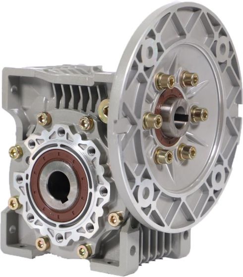
The gear reduction ratio in a right-angle worm type is based on the number of teeth on the mating worm wheel and the number of threads or “starts” on the worm. If the worm has two start sections and the mounting worm wheel has 50 teeth, the output gear ratio is 25:1 (50/2 = 25/1).
When a rotary system such as an engine or electric motor cannot supply the suitable output torque or speed, a gear reducer may present a good way. Planetary, Parallel shaft, and right-angle worm drives are typical reduction gearbox types for applying the gear reduction.
What are the Selection Criteria for Choosing a Reduction Gearbox?
Before buying a reduction gearbox, it’s essential to consider several factors including:
A reduction gearbox is employed to adapt the features (speed and torque) of the output and input axis of a mechanism. This is why you should know the rotation speed and torque.
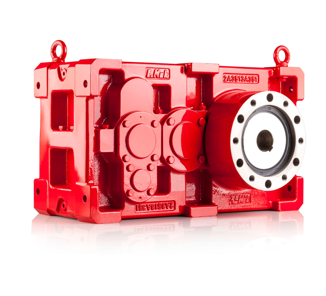
Therefore, it is appropriate to ask yourself about the torque aspect. A reducer improves the torque of the motor and so permits a receiving member to move under the effect of a new torque. Reduction gearbox manufacturers occasionally indicate the maximum and minimum torque (presented in newton meters, N.m) that can be supplied by each of their parts. The torque density changes based on the gear reducer. For instance, a planetary reduction gearbox has a high torque density.
The other aim of using a gear reducer is to decrease the motor speed. So, we recommend that you consider the perfect reduction ratio for your application. According to the rotational speed of the motor, the reduction ratio is utilized to identify the output rotational velocity. This information is also provided by constructors on their product pages. It is expressed in revolutions per minute (RPM).
Finally, you should ask yourself what type of reduction gearbox is most suitable for your application. The output and input shafts of your reducer can be parallel-shaft, coaxial, or orthogonal. This is based on your intended use.
Download What is a Reduction Gearbox? PDF
By clicking on this link, you can download the entire article as a PDF file.
Read More In linquip
- The Ultimate Guide to the Types of Gearbox
- Gearbox Components and Parts: Everything You Need to Know
- What is Planetary Gearbox and How Does it Works?
- Differences Between Worm and Helical Gear
- Types of Bevel Gears
- Top 10 Gear Manufacturers and Suppliers in the USA in 2022
- The Stages of Reverse Engineering an Industrial Gearbox
- The Difference Between Gearbox and Transmission
- What is Helical Gearbox?
- Differences Between Worm and Bevel Gear
- What is a Bevel Gear and How does it Work?
- What is a Worm Gearbox?
- Industrial Gearbox A Comprehensive Review on Features, Types and its Usability

