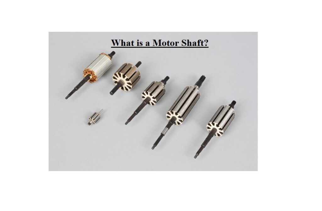
What is a Motor Shaft? Shafts are a key part of most rotating instruments. Once considering the most suitable substance for creating the electric motor shaft, there are a lot of aspects such as cost and material deficiencies. The motor shaft is the central section of the electric motor.
A motor’s shaft is a cylindrical part that protrudes from the motor and housing. The shaft’s function is to transfer energy from the motor to the intended use. Operating in relation to speed and torque are precision pins and shafts. Manufacturers, distributors, suppliers, and companies all provide a variety of motor shafts, and Linquip offers a vast assortment of Motor Shafts for Sale.
The website of Linquip includes a thorough list of shaft services for all OEM fleets. Linquip vendors can assist you with this. Please get in touch with Motor Shafts Experts to find out more about how to find a wide range of Service Providers who consistently deliver high-quality goods.
The motor shaft also is the carrier part for the laminated center of the rotor and thus transfers the electrically produced torque via a corresponding positive configuration in the transmission.
What is a Motor Shaft?
The main component in most rotating devices is the motor shaft. A shaft is a mechanical section for transforming the rotation and torque. Shaft size significantly influences the torque in these devices. Therefore, the precise modeling and prototyping of shafts are essential for all applications.
In addition to the need for mounting the rotor and a variety of attachments, the model of the motor shaft is very much based on the cooling concept selection of the electric device. Particularly with greater electric motors and thus longer and larger motor shafts, a hollow shaft enables new model matters both for lightweight construction and for the cooling system.
Some different performances are used to resume the transmission of the torque from electricity to the kinetic output in the transmission and thus to move the device. Based on the great rotation speed of up to more than 20.000 rpm and the large torques, the motor shafts should tolerate very high loads. This needs high-strength parts that still have to meet high requirements for lightweight modeling.
What Is Shaft Grounding?
Shaft groundings prevent the energy from harming delicate motor components. These devices offer a safer path to the ground by diverting electrical power away from delicate motor components with low resistance, such as motor bearings.
Construction of a Motor Shaft
Choosing the appropriate material can improve reliability. Once considering the best substance for the device and its shaft, you should primarily think about the cost.
The material used for a typical motor shaft is mild steel, but once high strength is needed, alloy steel such as chromium-vanadium, nickel, and nickel-chromium is used.
Most motor constructors apply SAE 1045 in either hot-rolled (HRS) or cold-rolled steel (CRS). C1045 is a moderate carbon, moderate tensile steel provided as forged or normalized. This steel demonstrates appropriate toughness, strength, and wear resistance. Visit here to see the manufacturing process of them.
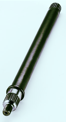
It is used for bolts, axles, crankshafts, forged connecting rods, light gears, torsion bars, guide rods, etc.
Other substances include sulfurized SAE 1137, SAE 1117, SAE 1144, cold-rolled SAE 1018, and hot-rolled SAE 1035. A ground stock of any substance is employed on particular CNC turning machines.
In general, the sulfurized and cold-rolled steels will increase prices relatively 15% more than HRS and will perform better. Machining trials are required to be implemented in order to control the extra cost. Because all shaft-turning devices perform differently, there is no established substance or machining maintenance.
On a cost-per-pound explanation, hot-rolled plain carbon steel is more cost-effective than cold-rolled sulfurized type. However, there are some drawbacks when we want to employ them. Hot-rolled material should be sized greater than cold-rolled form because of the lack of outer diameter (OD) monitoring in the rolling procedure.
Manufacturers of electric motors must evaluate whether the larger-size and lower-material-cost hot-rolled bar stock are more or less costly than cold-rolled bar stock.
Residual stresses, hard and soft spots, voids, and other substance deficiencies are typical with hot-rolled material, which makes it more problematic for machining. The issue with some high-strength steels is the hardest side is just the outside layers, so when the shaft is use, there is less strength.
Conducting trials will help you select the best substance between CRS, HRS, sulfurized, and non-sulfurized materials.
Industrial Electromechanical Repair Services (or IER Services) was presented in 2011 to supply effective, fast, repair services of electromechanical instruments of all kinds including DC and AC motors, variable frequency drives, pumps, dynamic balancing, and more. They also support shaft alignment services.
Not only do they provide their customers with quality motor shaft fixing, but they also provide special electric motor shafts used in other valves, pumps, motors, and hydraulics.
Materials Available in a Motor Shaft Construction
- Alloy Steel
- Aluminum
- Beryllium Copper
- Brass
- Bronze
- Carbon Steel
- Copper
- Nickel
Electric Motor Shaft Manufacturing
As discussed before, most motor manufacturers apply SAE 1045 in either cold-rolled (CRS) or hot-rolled steel (HRS). The hot-rolled carbon steel material, on a cost-per-pound foundation, is cheaper than the cold-rolled one. But there are some tradeoffs such as size considerations in the rolling process.
Constructors of electric devices estimate whether the lower-material-cost and larger-size hot-rolled bar stock are more or less expensive than cold-rolled bar stock.
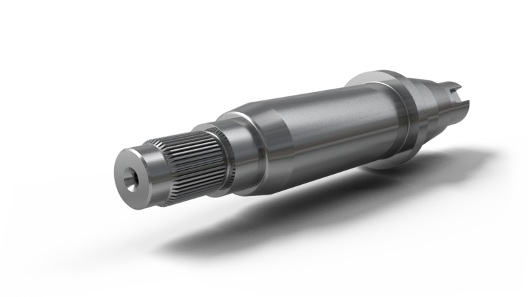
The hot-rolled substance, by the very nature of its features, has soft and hard spots, voids, residual stresses, and other material deficiencies, making it more problematic for machining. The main drawback with some high-strength steels is that the hardest section is just the outside layers, so once the shaft is machined down, the system will miss the strength.
Machine trials require to be conducted to choose the best option among various materials. (Because of the difficulties with HRS, some motor constructors will utilize sulfurized CRS).
Importance of Motor Shaft Alignment
Appropriate motor shaft alignment improves the performance life span of rotating devices. To obtain this, parts that are the most probably to fail must be designed accurately to perform within their acceptable design limits.
The Advanced Manufacturing Office of the U.S. Department of Energy has defined some information and tips regarding misalignment and key factors for alignment. The following information is the summarized tips we should consider about the importance of motor shaft alignment:
While misalignment has no measurable impact on the efficiency, an appropriate shaft alignment improves the efficient and smooth transfer of energy from the motor to the driven instrument. Otherwise, a wrong alignment happens once the centerlines of the driven equipment and the motor shafts are not in line with each other. Misalignment creates additional noise, vibration, premature failure of bearings, couplings or shafts, and coupling- and bearing-temperature increases.
Types of Motor Shaft Misalignment
There are three types of motor shaft misalignment:
- Angular misalignment happens while the motor is installed at an angle to the driven equipment. If the centers of the driven device and the motor shafts were to be extended, they actually cross each other, rather than run or superimpose along a standard centerline. The “space” (space difference between coupling faces) or slope difference of the motor shaft when compared with the slope of the fixed machine shaft can happen in the vertical direction, horizontal direction, or both. Angular misalignment particularly can result in severe damage to the driven instrument and the motor.
- Parallel misalignment occurs once the two shaft centerlines are in a parallel configuration, but not in the same line. There are two forms of parallel misalignment as shafts may be offset vertically (positioned at different elevations), horizontally (displaced to the left or right), or both.
- Combination misalignment happens once the motor shaft suffers from both parallel misalignment and angular one simultaneously. This is the most traditional misalignment situation encountered in the system.
Motor Shaft Misalignment of Couplings
Larger motors are typically coupled to their loads directly with flexible or rigid couplings. Flexible couplings tolerate small amounts of misalignment, while rigid types do not compensate for motor-to-driven-instrument misalignment. Flexible couplings also can decrease the vibration transferred from one section of equipment to another, and some can protect the driven equipment shaft from stray electrical currents. Even flexible couplings need some alignment considerations, presented in the instruction sheet for them.
It is a mistake to rely on the flexibility of coupling for additional misalignments since flexing of the shaft and the coupling will exert loads on the driven equipment and motor bearings. These loads may cause shaft breaking or cracking, premature bearing, seal or coupling failure, and additional axial and radial vibrations. Secondary impacts contain loosening of foundation bolts and broken or loose coupling bolts. Performance life is reduced when shafts are misaligned.
Proper alignment is practically difficult to obtain without employing alignment equipment such as laser alignment tools or dial indicators. The appropriate motor shaft alignment procedure is to monitor the driven equipment primarily since moving a pump, for instance, would stress the mounted piping. The next tip is setting the coupling to the driven equipment. The motor must then be moved into suitable alignment and connected to the coupling.
After the instrument has been performed long enough to become temperature-stabilized, we should turn it off and immediately control the alignment. Alternatively, we can control the relative positional modifications of the machines with a laser system equipped to function. Because of the thermal growth, devices aligned in the “cold” pre-operating state are almost often out of alignment when working temperatures are attained. Many device constructors publish thermal offset values, so the alignment technician can revise them for thermal growth during the initial alignment procedure.
Suggested Actions of Motor Shaft Misalignment
Here, some suggested actions of motor shaft misalignment are presented:
- Check shaft alignment of all production-critical instruments annually.
- Check newly installed instruments for alignment variations due to foundation settling after 3 to 6 months of function.
- Control the vibrations and the increasing vibration trends as the main sign of misalignment. Misalignment might be caused by insufficient bolt tightening, foundation settling, or output shaft faults.
- Apply predictive maintenance methods including frequency spectrum analysis and vibration tests to distinguish between shaft misalignment, bearing wear, or electrically caused vibrations.
What are Electric Motor Shaft Circulating Currents?
Motor shaft circulating currents occur because of “dissymmetries” in the magnetic paths across the rotor and stator iron. As the rotor circulates through the stator and once the stator’s magnetic field moves, small differences in the magnetic “reluctance” of the core components produce small voltages between the sections of the shaft.
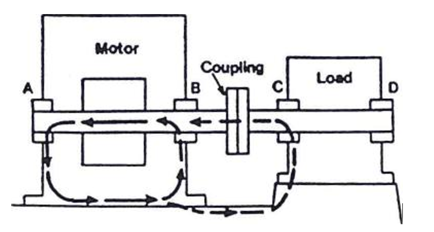
As you can understand from the above discussion, the circulating currents are the result of the electric motor’s electrical modeling. This is why some constructors will design the motor with an insulated bearing housing; bearing or endbell. These special designs are generated to interrupt the closed path for circulating currents across the bearings to the grounded motor structure.
These currents will jump through ball-bearing spaces or intermittently break across sleeve-bearing oil films. The result is electric arcing on the greatly polished surface of the races or balls in ball bearings which causes early failure and fatigue.
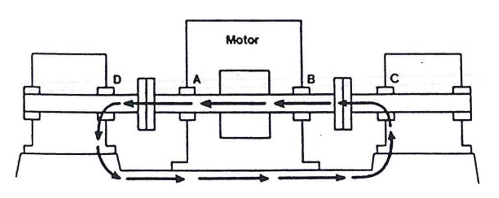
It should be considered that motor shaft circulating currents can also be caused by magnetizing the shaft (i.e. magnet) from external supplies such as welding, etc. There are also static charges that can result in a shaft circulating current problem. As the shaft electrically charges, then discharges across the bearings causing damage.
It is also worth considering that shaft circulating currents are becoming more common in smaller horsepower electric devices because of the popularity of variable frequency controllers. A variety of instruments are now being employed, such as the AEGIS Shaft Grounding Ring, which are constructed and modeled to help protect the motor’s themselves and remove the circulating currents.
Characteristics of a Motor Shaft
According to the user demands, the motor shafts can be constructed as hollow shafts as well as solid shafts.
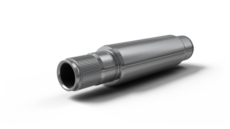
- Lightweight design can be used employing a tube and as a built version.
- A combination of various materials is possible.
- Motor shafts are ready for installation or as a semi-finished component close to the final contour.
- Low weight (conserve resources) and high transmission capacity
- Splines can be changed according to customer requirements
Download Motor Shaft PDF
Read More In Linquip
- What is ECM Motor : Discover the working, the Good and the Bad
- 10 Types of CNC Machine + Applications & PDF
- 13 Parts of CNC Machine + Function & PDF: A Clear Guide
- What Is CNC Machining & How Does It Work? (A Comprehensive Guide)
- Working Principle Of DC Motor: 2022 Complete Guide
- Working Principle of Stepper Motor: 2022 Ultimate Guide
- Working Principle of AC Motor: 2022 Ultimate Guide
- Working Principle of Induction Motor: 2022 Full Guide
- DC Motor Efficiency: Calculation: Formula & Equation
- Efficiency of Induction Motor: Calculation & Equation
- What is Gear Shaft? Clear Principle & Advantages
- What is a Reduction Gearbox?
- What is a Series Wound DC Motor?
- What is Axial Flux Motor and It’s Working Principle?



I have read your article, and it really helped me understand this information. Keep sharing. Have a great day!
Thanks for visiting our website and leaving your comment, Noel! You are encouraged to visit Linquip Tech News, where you can find similar posts.