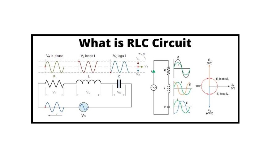
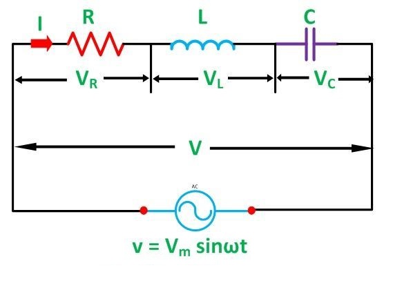
What is an RLC Circuit, and how does it work? RLC Series Circuit is formed when a pure inductance of L Henry, a pure resistance of R ohms, and a pure capacitance of C farads are connected in series with each other. The current flowing through each element of the circuit will be the same as the total current I flowing in the circuit because all three elements are connected in series.
What is RLC Circuit?
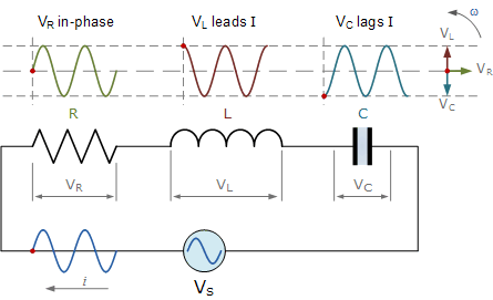
The RLC Circuit is depicted in the diagram below:
Series RLC Circuit Analysis
A resistance, a capacitance, and an inductance are connected in series across an alternating supply in a series RLC circuit. When attached to a sinusoidal alternating supply, the three main passive components of resistance, inductance and capacitance have highly distinct phase connections to each other.
The voltage waveforms in a pure ohmic resistor are “in-phase” with the current waveforms. The voltage waveform in a pure inductance “leads” the current by 90o, giving us the expression: ELI. The voltage waveform in a pure capacitance “lags” the current by 90o, giving us the expression: ICE. Visit here to see the principle of an RLC circuit completely.
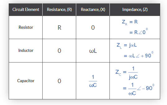
This Phase Difference (Φ) is determined by the reactive value of the components used, and hopefully, by now we know that reactance (X) is zero if the circuit element is resistive, positive if the circuit element is inductive, and negative if the circuit element is capacitive, resulting in the following impedances:
Element Impedance
Instead of evaluating each passive part independently, we may use a series RLC circuit to connect all three. The analysis of a series RLC circuit is similar to that of the dual series RL and RC circuits we looked at earlier, except that this time we must account for the magnitudes of both XL and XC in order to determine the overall circuit reactance. Because they comprise two energy storage elements, an inductance L and a capacitance C, series RLC circuits are classified as second-order circuits. Take a look at the RLC circuit below.
Series RLC Circuit
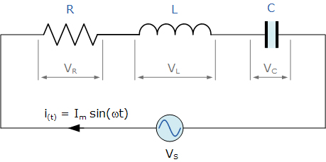
The single loop in the series RLC circuit above has the same instantaneous current flowing through it for each circuit element. The sinusoidal response of a series RLC circuit will change with frequency because the inductive and capacitive reactances XL and XC are functions of the supply frequency. The unique voltage drops across each R, L, and C circuit element will thus be “out-of-phase” with one another, as defined by:
i(t)={i}_{max}sin(\omega t)
- VR is the instantaneous voltage across a pure resistor that is “in-phase” with the current.
- VL is the instantaneous voltage across a pure inductor, and it “leads” the current by 90 degrees.
- VC, the instantaneous voltage across a pure capacitor, is 90 degrees behind the current.
As a result, VL and VC are 180 degrees out of phase and in opposition to one another. This can be shown as follows for the series RLC circuit:
The three separate component voltages, VR, VL, and VC, make up the amplitude of the source voltage across all three components in a series RLC circuit, with the current common to all three components. The current vector will be used as a reference in the vector diagrams, and the three voltage vectors will be shown with respect to this reference, as shown below:
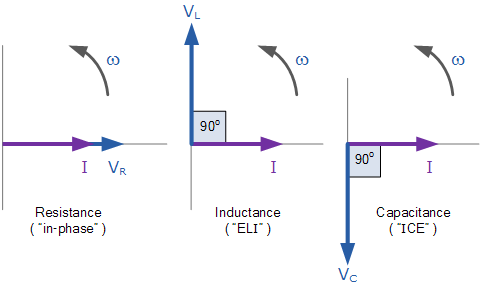
As the three voltage vectors point in different directions to the current vector, we cannot simply sum VR, VL, and VC to determine the supply voltage, VS, across all three components. As a result, we must calculate the supply voltage, VS, as the Phasor Sum of the three component voltages vectorially combined.
For both loop and nodal circuits, Kirchhoff’s voltage law (KVL) indicates that the sum of voltage drops around the loop equals the sum of the EMFs. The amplitude of the source voltage, VS, is obtained by applying this law to these three voltages.
Instantaneous Voltages for a Series RLC Circuit
{V}_{S}=IR+L\frac{di}{dt}+\frac{Q}{C}
Combining the three independent phasors above and vectorially adding these voltages yields the phasor diagram for a series RLC circuit. Because the current flowing through the circuit is carried by all three circuit elements, we may use it as a reference vector, with the three voltage vectors shown at their corresponding angles in relation to it.
By adding the sum of two of the vectors, VL and VC, to the remaining vector VR, the resultant vector VS is formed. The phase angle of the circuit will be the result of the angle obtained between VS and I as shown below.
Phasor Diagram for a Series RLC Circuit
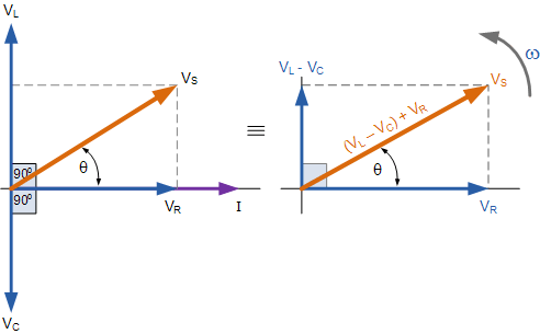
The voltage vectors produce a rectangular triangle, as shown in the phasor diagram on the right-hand side, with a hypotenuse VS, horizontal axis VR, and vertical axis VL – VC. Hopefully, you’ll see that this creates our old favorite, the Voltage Triangle and that we can utilize Pythagoras’ theorem on this voltage triangle to achieve the value of VS as illustrated mathematically.
Voltage Triangle for a Series RLC Circuit
{V}_{S}=\sqrt{{V}_{R}^{2}+({V}_{L}-{V}_{C})^{2}}
Please keep in mind that when applying the above equation, the final reactive voltage must always be positive, i.e. the smallest voltage must always be subtracted from the greatest voltage; we cannot have a negative voltage added to VR, therefore VL – VC or VC – VL is correct. Otherwise, VS will be incorrectly calculated if the smallest value is subtracted from the greatest.
We already know that the current in a series RLC circuit has the same amplitude and phase in all of its components. The voltage across each component may thus be mathematically characterized in terms of the current flowing through it, and the voltage across each element can be described as:
{V}_{R}=iRsin(\omega t+0)=iR
{V}_{L}=i{X}_{L}sin(\omega t+90)=i.j\omega L
{V}_{C}=i{X}_{C}sin(\omega t-90)=i.\frac{1}{j\omega C}
By adding these numbers into the Pythagoras equation for the voltage triangle above, we get:
{V}_{S}=I\times Z, where; Z=\sqrt{{R}^{2}+({X}_{L}-{X}_{C})^2}
As a result, we can see that the source voltage amplitude is proportional to the current flowing through the circuit. The Impedance of the circuit is the proportionality constant that is determined by the resistance, as well as the inductive and capacitive reactances.
The resistance to current flow is made up of three components in the series RLC circuit above, XL, XC, and R, with the reactance, XT, of any series RLC circuit being defined as XT = XL – XC or XT = XC – XL, whichever is higher. As a result, the circuit’s total impedance is thought of as the voltage source required to generate a current through it.
The Impedance of a Series RLC Circuit
Because the three vector voltages are out of phase, XL, XC, and R must be out of phase as well, with the relation between R, XL, and XC being the vector sum of these three components. This will give us the overall impedance of the RLC circuit, Z. An Impedance Triangle, as shown below, can be used to draw and describe these circuit impedances.
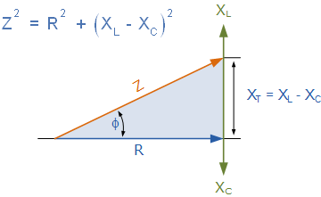
The angular frequency (ω) affects the impedance Z of a series RLC circuit, as do XL and XC. When capacitive reactance exceeds inductive reactance (XC > XL), the entire circuit reactance is capacitive, resulting in a leading phase angle.
Similarly, if the inductive reactance is greater than the capacitive reactance, XL > XC, the entire circuit reactance is inductive, resulting in a lagging phase angle in the series circuit. If the two reactances are the same and XL = XC, the angular frequency at which this occurs is known as the resonant frequency, and it generates the effect of resonance, which we will look at in more detail in another post.
The magnitude of the current is then determined by the frequency used in the series RLC circuit. When Z is at its maximum, the current is at its lowest, and when Z is at its lowest, the current is at its highest. As a result, the above impedance equation may be rewritten as:
Impedance, Z=\sqrt{{R}^{2}+(\omega L-\frac{1}{\omega C})^2}
In the impedance triangle, the phase angle between the source voltage, VS, and the current, I is the same as the angle between Z and R. This phase angle can be positive or negative depending on whether the source voltage leads or lags the circuit current, and it can be computed analytically using the impedance triangle’s ohmic values as follows:
cos(\phi )=\frac{R}{Z}, sin(\phi )=\frac{{X}_{L}-{X}_{C}}{Z}, tan(\phi )=\frac{{X}_{L}-{X}_{C}}{R}
Applications of RLC Circuit
The RLC circuit can be used in the following ways:
- It performs the function of a variable tuned circuit.
- Depending on the frequency, it can be used as a low pass, high pass, bandpass, or bandstop filter.
- The circuit can be used as an oscillator as well.
- Circuit with a voltage multiplier and a pulse discharge.
- Resonant RLC circuits are utilized in a variety of applications, including oscillator circuits, radio receivers, and television sets for tuning.
- The principal application of the series RLC circuit is in signal processing and communication systems.
- Voltage magnification is achieved using a series resonant RLC circuit.
- Induction heating uses series RLC circuits.
The RLC circuit, principle, analysis, and applications of RLC circuits are all covered in this post. We hope the information provided in this post aids in providing useful knowledge and understanding of them. Furthermore, you can leave a remark in the box below if you have any questions about this post or the electrical and electronic projects.
Buy Equipment or Ask for a Service
By using Linquip RFQ Service, you can expect to receive quotations from various suppliers across multiple industries and regions.
Click Here to Request a Quotation From Suppliers and Service Providers
Read More In Linquip
- Types of Electric Circuits: All Classification with Application
- How does a Circuit Breaker Work?
- What is Linear Circuit
- What is RL Circuit
- What is RC Circuit?
- What is RLC Circuit
- What is Capacitive Circuit?
- Types of Resistor: Classification, Application, and Finally Clarification
- What is Parallel Circuit? Definition & Example
- What is Series Circuit? Definition & Example
- What is Closed Circuit? Definition & Example
- What is Short Circuit? A Clear Definition & Protection Guide
- Difference Between Linear and Nonlinear Circuits
- What are the Differences Between Series and Parallel Circuits?
- The 8 Best Circuit Breaker Locators in 2022
- What is LC Circuit? Formula, Equitation & Diagram
- What is Open Circuit? Diagram & Example
- What is Inductive Circuit?
- What is AC Circuit and Its Characterization?

