The efficiency of Stirling Engine – A Stirling engine is a heat engine that operates by compressing and expanding air or another fluid (the working fluid) at different temperatures in a cyclic pattern, converting heat energy to mechanical work. The Stirling engine, in particular, is a closed-cycle regenerative heat engine with a constant gaseous working fluid. In this application, closed-cycle refers to a thermodynamic system in which the working fluid is permanently kept within the system, and regeneration refers to the employment of a specific form of an internal heat exchanger and thermal store, referred to as the regenerator. A Stirling engine is distinguished from other closed-cycle hot air engines by the presence of a regenerator. You can find various types of Stirling engines from various manufacturers in the Linquip.
You will find all the information about Stirling engines and associated equipment and devices on Linquip’s website. With regards to any questions you might have regarding any kind of engine, you are welcome to turn to the Linquip team of experts at any time. If you wish to gain a better understanding of these engines, Linquip’s article “What Is A Stirling Engine?” would be a good starting point.
The Linquip website has a feature called Linquip Expert, where you can sign up if you want to learn more about and discover all the features available through the Linquip website. You must demonstrate your skills to potential clients, specifically depending on what equipment you use. Have you considered the idea of guest posting on our website? We invite you to participate in Linquip’s Guest Posting program and submit your content directly to the platform.

Classification of Stirling Engines
Robert Stirling invented the first real-world example of a closed-cycle hot air engine in 1816, and Fleeming Jenkin proposed as early as 1884 that all such engines be referred to as Stirling engines. This suggestion did not go over well, and the many varieties on the market were still referred to by the names of their particular designers or manufacturers, such as Rider’s, Robinson’s, or Heinrici’s (hot) air engine.
In the 1940s, Philips was looking for a name for its version of the ‘air engine,’ which had already been tested with working fluids other than air, and in April 1945, they settled on the ‘Stirling engine.’ Graham Walker, however, had cause to rue the fact that words like hot air engine remained interchangeable with Stirling engine, which was used frequently and indiscriminately, a condition that still exists over thirty years later.
The Stirling engine, like the steam engine, is classified as an external combustion engine because all heat transfers to and from the working fluid occur through a solid boundary (heat exchanger), effectively isolating the burning process and any contaminants it may generate from the engine’s working parts. In an internal combustion engine, heat is generated by the combustion of a fuel within the working fluid’s body. The Stirling engine can be implemented in a variety of ways, although the majority of them fall under the category of reciprocating piston engines.

Theory of Working
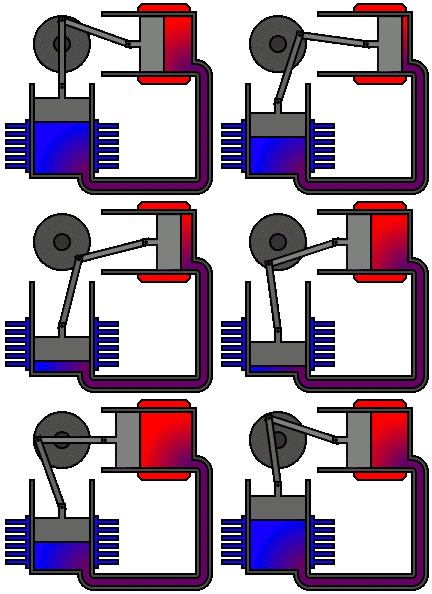
Four thermodynamic processes occurring on the working fluid make up the idealized Stirling cycle:
- Isothermal expansion. The gas expands near-isothermally while absorbing heat from the hot source, and the expansion space and accompanying heat exchanger are kept at a constant high temperature.
- Constant-volume heat-removal. The gas passes through the regenerator, which cools it and transfers the heat to the regenerator for use in the following cycle.
- Isothermal compression. The gas experiences near-isothermal compression, rejecting heat to the cold sink because the compression area and related heat exchanger are kept at a constant low temperature.
- Constant-volume heat-addition. The gas returns to the regenerator, where it recovers much of the heat lost in process two and then heats up as it travels to the expansion space.

The engine is built so that the working gas is compressed in the colder parts and expanded in the hotter parts, resulting in a net conversion of heat to work. In comparison to simpler hot air engines that lack this feature, the Stirling engine’s thermal efficiency is improved by an internal regenerative heat exchanger.
The Stirling engine transforms thermal energy into mechanical energy by using the temperature differential between its hot and cold ends to generate a cycle of a constant amount of gas being heated and expanded, then cooled and compressed. The thermal efficiency increases as the temperature difference between the hot and cold sources grows. Although the greatest theoretical efficiency is equal to that of the Carnot cycle, real-world engine efficiency is lower due to friction and other losses.
Because the Stirling engine is a closed cycle, it uses a constant mass of gas known as the “working fluid,” which is usually air, helium, or hydrogen. In a typical operation, the engine is sealed, and no gas enters or exits; unlike other types of piston engines, no valves are required. Cooling, compression, heating, and expansion are the four fundamental processes that the Stirling engine, like most heat engines, cycles through.
The gas is moved back and forth between hot and cold heat exchangers, frequently with a regenerator between the heater and cooler. The cold heat exchanger is in thermal contact with an outer heat sink, such as air fins, whereas the hot heat exchanger is in thermal contact with an external heat source, such as a fuel burner. A change in gas temperature results in a corresponding change in gas pressure, while the piston’s motion causes the gas to expand and compress alternately.
The gas behaves according to the gas laws, which describe how the pressure, temperature, and volume of a gas are related. Because the gas is in a sealed chamber, the pressure rises when it is heated, and this pressure operates on the power piston to produce a power stroke. When the gas cools, the pressure reduces, which means the piston has to work less on the return stroke to compress the gas. The difference in work between the strokes results in a power output that is a net positive.
The action is slightly different when one side of the piston is exposed to the environment. When the sealed volume of working gas comes into touch with the hot side, it expands, exerting force on the piston as well as the surrounding atmosphere. When the working gas comes into touch with the cold side, its pressure falls below atmospheric pressure, and the atmosphere exerts on the piston, causing the gas to work.

Thermodynamic Theory of the Ideal Stirling Engine
Stirling engines are one of those machines that have captivated many engineers over the years, particularly while we’re young and impressionable before we’ve become too jaded about the world. It’s also one of those technologies that, despite YouTubers’ shouts of “free energy,” hasn’t taken off. It’s clear that it’s not the right solution for many problems, but it’s a neat engine for some applications.
A Stirling engine is a type of heat engine developed by Robert Stirling in 1816 that can convert the passage of heat into mechanical work (such as spinning a crankshaft). The important concept is “heat flow”; for this flow to occur, there must be two independent “reservoirs,” and the temperatures in these reservoirs must be different. If you placed a thermal conductor between the two reservoirs, they would gradually reach the same temperature, suggesting that energy is “flowing” from the hot to the cold reservoir.
Thermal Efficiency Remarks
Thermal efficiency is the ratio of usable work to heat transfer into the engine. Consider it a ratio of what you want (valuable mechanical work) to what it costs (heat transfer into the engine).
\eta=\frac{Useful~Mechanical~Work}{Heat~Transfer~From~the~Hot~Section}
It is unlikely to achieve a level of efficiency greater than one. If the efficiency is 1, all heat transfer into the engine is converted to meaningful work, and no heat is transferred to the cool portion. An efficiency of 0 means that no beneficial work is done and that all heat transfer from the hot part is merely transferred to the cold section of the engine. If you put two hot and cold bricks next to each other within a properly insulated box and left them there for a while, you’d come back to discover two warm bricks. This is a heat engine with an efficiency of 0; the heat was transmitted from the hot brick to the cold brick in a 1:1 ratio, resulting in no meaningful work.
Efficiency can never equal 1; sorry for the inconvenience, but the second law of thermodynamics is total creep. The Carnot efficiency is named after Nicolas Léonard Sadi Carnot, and it is derived from the relation that limits physically possible efficiency levels. Without violating the second rule of thermodynamics, he was able to predict the highest efficiency that could be expected. Only the temperatures of the hot sector and the cold region between which a particular heat engine is operating can be used to compute the Carnot efficiency. As a result, you’ll never have a heat engine that doesn’t send some heat to the chilly region.
\eta_{Carnot}=\frac{Cold~Temperature}{Hot~Temperature}

When the feasible Carnot efficiency is plotted against the hot section temperature, the wider the temperature difference between the hot and cold sides, the higher the possible efficiency. Not all engines can achieve Carnot efficiency theoretically (much alone, realistically). Even in an ideal world, the perfect diesel engine will never be able to match the theoretical Carnot heat engine’s efficiency. Other types of heat engines can theoretically match the Carnot engine’s performance. One example of this is the Stirling engine. As a result, at a particularly hot section and cold section temperature, the Carnot efficiency is equal to the Stirling efficiency between these hot and cold sections.
\eta_{Stirling}=\eta_{Carnot}
A Stirling engine must have a hot segment that is heated continuously from some source and a cold part that is chilled in some way to run continuously. If you don’t alternate between heating and cooling the hot and cold parts, soon enough heat will be passed between the two, and you’ll only have two warm sections. When this happens, the temperature disparity between sections vanishes, efficiency plummets, and no heat is transported through the engine because there is no temperature differential.
Real Stirling Configurations
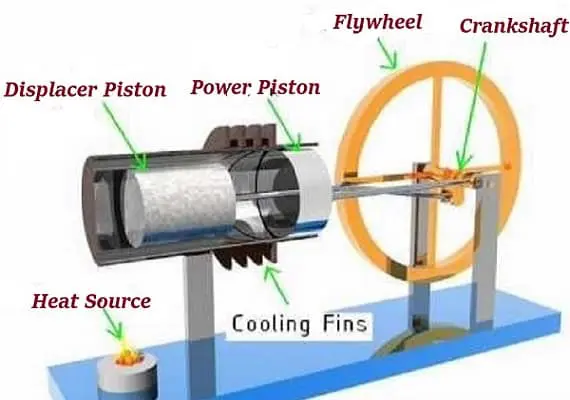
Most Stirling engines contain a “displacer” piston that simply prohibits contact between the working fluid and either the hot portion or the cool section depending on its location to check when heat is transported to or from the working fluid. To modify the volume of the system, a power piston that reciprocates in a cylinder bore is frequently used, and this piston is often coupled to a crankshaft to collect the usable work.
To achieve the effects needed during a Stirling cycle, an engineer can mechanically link the power piston, heat exchangers, and displacer piston in a variety of ways. Because no mechanism can completely replicate the motions required, one source of loss in actual Stirling engines is the “approximation” of the cycle that is required to construct a real machine. The beta type and the alpha type are two of the most prevalent engine setups.


Summary of Equations
The following formulas can be utilized to compute the fluid characteristics in all of the distinct states of a Stirling cycle:
The subsequent formula can also be used to calculate the amount of beneficial work generated. The acronym CR stands for “Compression Ratio” (max engine volume divided by min engine volume). Please note that this formula calculates the amount of work performed per unit mass of working fluid per Stirling engine revolution. Temperatures must be measured on an absolute scale as well (i.e. Rankine or Kelvin).
W_{Total}=T_C R(ln(\frac{1}{CR}))+RT_H (ln(CR))
It’s vital to remember that all of these figures represent the ideal Stirling cycle, which will never exist in reality; all real engines are approximations of ideal thermodynamic cycles. Knowing how to change these ideal interactions to represent the real world is a completely different topic, one that may be covered in a future essay!
You can find more information about the Stirling cycle in this nice video.
Do Stirling Engines Have a More Efficient Power Output Than Solar Panels?
A Stirling engine converts sunlight into energy much more efficiently than most photovoltaic panels and concentrating solar power plants, whether using parabolic troughs or towers.
Which Stirling Engine Design Is the Most Efficient?
The MOD II automotive engine produced in the 1980s was among the most efficient Stirling engines ever manufactured. The engine’s peak thermal efficiency was 38.5%. This is significantly higher than a modern spark-ignition (gasoline) engine with a peak efficiency of 20-25%.
Download Efficiency of Stirling Engine PDF
To keep this PDF document for future reference, you can download it to your computer. You can do this by clicking on the download link below.
Buy Equipment or Ask for a Service
By using Linquip RFQ Service, you can expect to receive quotations from various suppliers across multiple industries and regions.
Click Here to Request a Quotation From Suppliers and Service Providers
Read More In Linquip
- Diesel Engine Working: everything you need to know
- How do Valves Work in an Engine?
- The 10 Best Diesel Engines
- Quick Guide: The Difference Between Gas Turbine and Diesel Engine
- Differences Between Motor and Engine
- Differences Between Engine and Transmission
- The Difference Between Diesel Engines and Gas Engines: Discover the distinction, decide the best
- The Difference Between Diesel Engine and Petrol Engine: which one best works for you?
- Diesel Engine Working: everything you need to know


Very nice summary of Stirling engines. I’ve been thinking of alternate styles using blowers to transport working fluid to the hot and cold heat exchangers. I really liked your moving diagrams. One note is that automotive SI engines have had peak thermal efficiencies over 36% for decades and TOYOTA’s Atkinson cycle engine is now at 41%, max, if memory serves.