Several different parts of submersible pump work together to ensure the overall functionality of the submersible pump. Although some parts take center stage, if you take away one part, you could be in danger along with your pump.
Linquip website is a great place to find out all the answers to your questions about submersible pumps. We have a team of experts who would be pleased to assist you with any questions you might have regarding submersible pumps. As a starting point, you might want to read Linquip’s article titled “Submersible Pump: Working Principles, Function, and Diagram” to gain an understanding of how these pumps work.
Do you have any experience working with submersible pumps in the past? We provide a comprehensive selection of Submersible Pumps Products at Linquip, from which you will be able to find the exact product that you are looking for. Are you looking for a submersible pump right now? What type of pump do you need? Linquip provides you with free access to the full database of all possible Submersible Pump Devices for Sale. By using Linquip, you have the opportunity to request a free quote for the price of submersible pumps from all the available Submersible Pumps Suppliers and Companies.
A variety of submersible pump components are examined in this post in terms of their roles and how they work together. Read on to learn more.
⇒ View a Comprehensive List of Submersible Pumps for Sale and Their Suppliers ⇐
A Brief Introduction
Pumps are devices used to transfer fluids from one place to another. Various types of pumps are used in different industries around the world. One popular type is the submersible pump. Submersible pumps are multistage centrifugal pumps. They are also called well pumps.
When a submersible pump works, it pushes water toward the surface rather than pulling it. These pumps have hermetically sealed motors to help push fluid to the surface. They are the most popular type of centrifugal pump.
Submersible pumps are primarily used to pump water from wells. Water is pushed toward the surface of the water by transforming rotatory motion into kinetic energy, and the diffuser blades further convert this kinetic energy into pressure energy.
One of the most notable advantages of this pump is that it prevents cavitation. Since they are completely submerged in water, these pumps are known as submersible pumps. Consequently, these pumps are designed primarily to pump water from tanks, wells, or other vessels by submerging it into the water or other liquid. Additionally, the pumps can be used in hot water-heavy oil applications in which underground pressurized liquid powers a hydraulic motor instead of an electric motor.
Due to its complete submersion in fluid, this pump does not usually require priming. This high-quality pump, however, creates much complexity and cannot operate without problems, so it is not taken out of the water.
They are useful in many situations as they prevent pump cavitation. Submersible pumps have many applications in various industries. Single-stage submersible pumps are used in industries such as sewage and drainage, while multi-stage pumps are used in the industrial, commercial, municipal and residential sectors.
Function of Submersible Pumps
Submersible pumps operate differently than jet pumps. Since jet pumps transfer fluid by pulling it, whereas submersible pumps do so by pushing it. The submersible water pump has a sealed motor attached to it. This is a centrifugal pump. As a result, it works very much like other types of centrifugal pumps. A submersible pump is completely submerged underwater. Submersible water pumps push water toward the surface as they work.
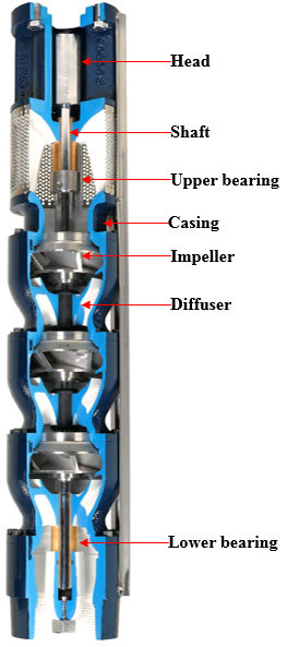
Water from a well or reservoir enters the pump through the foot valve and strikes the impeller. There are multiple fixed blades on an impeller, which makes it a rotatory unit. An electric motor drives the impeller. As the shaft rotates, the impeller rotates as well.
By hitting the blades of the impeller, the water kinetic energy is converted to speed, and the water speeds up. The water passes through the impeller and into the diffuser, where the speed of the water is further converted into pressure energy. Using this diffuser, water is pushed to desired pressures; then, pressurized water leaves the pump through the outlet valve. This is how submersible pumps force water to the surface.
Components of Submersible Pump
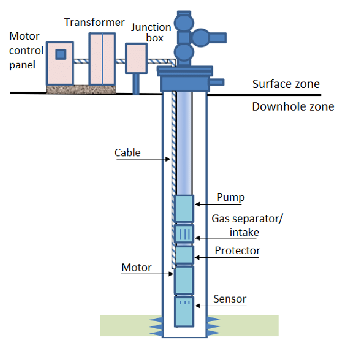
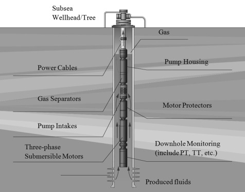
Submersible pumps are typically composed of an electric motor, a seal section, an intake section, a multistage centrifugal pump, an electric cable, a control panel installed on the surface, and transformers. Additionally, the installation will usually include mechanisms for securing the cable along with the tubing, wellhead supports, check and bleeder valves, and so on. A downhole sentry may be used to sense bottom-hole pressure and temperature.
The downhole equipment is submerged in well fluid and suspended from the wellbore. Setting the depth in the well or the bottom hole pressure is not problematic as the seal section equalizes the internal pressure in the motor with the submersion pressure in the well. It is possible to install the motor in crooked or directional holes.
Motor
Pumps are driven by submersible electric motors. The motor rotates at the rate of 3450-3500 RPM at 60 Hz (2875-2925 RPM at 50 Hz) at full load. It is a two-pole, three-phase squirrel-cage induction motor. It is designed to operate at a wide range of voltages and currents.
A carbon steel housing encloses the stator laminations and windings. Assemblies for rotating are made up of rotors mounted on and keyed to shafts made from high-strength steel supported by bearings in intermediate positions. To obtain the required power, the motor length and number of rotors are increased. A single-section motor usually has a maximum overall length of 33 feet to facilitate its assembly and transportation.
Motors may be made up of one motor or multiple motors bolted together simultaneously.
Seal Section
In general, seals perform the following basic functions:
- For housing the pump thrust bearing, which carries the axial thrust generated by the pump.
- Designed to keep well water from entering the motor.
- In order to eliminate the pressure difference across shaft seals, it is necessary to equalize the motor’s internal pressure with its wellbore pressure.
- The oil expansion and contraction due to the heating and cooling of the motor when the unit is running or shutting down should be compensated.
With the expansion bag, the motor oil is further shielded from the well fluid. Mechanical shaft seals prevent the entrance of well fluid along the shaft. The seal section is equipped with a tilt-pad thrust bearing with high capacity.
Seals can either be incorporated into a single unit or can be added to a tandem arrangement if it is desired to add additional seals and oil volume capabilities for high horsepower motors or more protection.
Intake Section, Gas Separator
Intake Sections serve as suction manifolds for supplying well fluid to pump impeller eyes. If the well conditions allow, it can be a gas separator. In applications with high GOR and low bottom-hole pressures, the well fluid may contain considerable amounts of free gas, which can negatively affect pump performance. Usually, these cases are handled by replacing the intake section with a gas separator.
A gas separator is used to separate free gas from well fluid once it enters the pump. The well fluid (which consists of free gas and liquid) is subjected to centrifugal forces when it passes through the impeller. Liquids, owing to their density, are thrown to the outer edges of the impeller while gas forms a core near the center. The gas-filled annular space is vented, while the gas-free liquid is introduced into the pump impeller eye.
Based on the field conditions, a gas separator or a basic intake section can be added to the pump.
Multistage Centrifugal Pump
Submersible pumps consist of multistage centrifugal pumps. An impeller and a diffuser are the parts of a stage. An impeller rotates while a diffuser is stationary. The limited diameter of well casings limits the amount of lift that can be developed by a stage, so multiple stages are stacked together to achieve the high head requirements of artificial installations.
Pumps can be assembled either as floated impeller pumps or as fixed impeller pumps, depending on how axial thrust is handled. The impellers of a floated pump can move axially along the shaft. In operation, the impeller either rests on the downthrust pad or on the upthrust pad depending on the flow rate. Thus, the axial thrust generated by each impeller is transferred to the upthrust or downthrust washers attached to each impeller and diffuser pad. Due to the differential pressure across the shaft, there is an axial force, which is exerted on the thrust bearing in the seal section.
An impeller on a fixed pump cannot move axially since it is attached to the shaft. An external thrust bearing installed in the seal section carries the total axial thrust produced by the impellers and the pressure difference.
Check and Bleeder Valves
Usually, a check valve is installed 2-3 tubing joints over the pump assembly and helps ensure that there is a full column of fluid above the pump. Without a check valve, fluid from the tubing can flow through the pump when the motor is shut off, causing the unit to rotate in the opposite direction. Starting the unit while its reverse rotation is in progress, can severely damage the motor, thrust bearings or shafts.
For cases without a check valve, it is necessary to wait a sufficient amount of time for the tubing fluid to return before attempting to restart the motor. Reverse rotation speed and duration are dependent on a variety of factors such as depth, tubing size, pump size and type, tubing restrictions, etc. You should wait a minimum of thirty minutes before restarting the system.
The bleeder valve must be installed immediately above the check valve in installations with a check valve to prevent pulling wet tubing. If the fluid appears in the tubing when pulling it, the break-off plug in the bleeder valve must be sheared.
Electric Cable
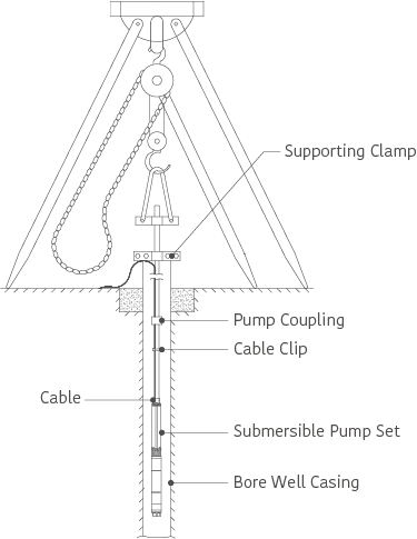
The submersible motor receives power through an electric cable. A range of conductor sizes allows it to be matched efficiently to motor requirements. It may also be clad in galvanized steel, bronze, or monel armor that can withstand the hostile conditions of an oil well.
Cables can be installed in wells with temperatures above 300°F, depending on the type of insulation used. Where clearance is a problem, a flat cable can be used instead of a round cable. Cable clamps or bands are used to secure the cable along with the pump and tubing.
Surface Equipment
Transformers, a junction box, and a control panel are typically included in the surface equipment. A wide range of sizes and accessories are available to accommodate different installations. The standard control panels have weatherproof features. It may be as simple as an assembly with magnetic contactors and overload protection, or it may be as complex as a wiring assembly with fused disconnects, recording ammeters, underload and overload protection indicators, and instruments for automatic remote control.
Easy Tie Adapters
The easy tie adapters thread into the check valve discharge on the submersible pump, and connect to the poly riser pipe. The pitless adapter at the wellhead can then be threaded with a second adapter, which connects to the poly riser pipe. The hole in the lug, or the rope eye, provides a means to secure the safety rope or cable to the wellhead or to secure the submersible pump to the wellhead in the event of a failure. Both bronze and stainless steel versions are available.
Clamps
Designed to secure poly pipe to barbed insert fittings, these clamps provide a positive watertight seal that is pull-off proof. For water well installations or when corrosion resistance is required, a stainless steel clamp made from grade 300 stainless steel will last the life of the system.
Heat Shrink Splice Kits
A heat shrink splice kit is designed to connect the pump cable and the motor leads under water. To make the connection, the cables are cut in staggered positions to reduce the outer diameter. The splice must be protected from abrasion prior to being lowered into the well in order to reduce the risk of damage.
Torque Arrestors
A torque arrestor prevents the well casing from twisting and thus keeps the submersible pump centered. A torque arrestor is typically mounted directly above the pump.
Safety Rope
The safety rope is connected directly to the submersible pump and attached to the wellhead. Its main purpose is to prevent the separation of the pipes, which could lead to the loss of a pump at the bottom of the well. If the riser pipe fails, a safety rope can also be used as a backup so the installer can remove the pump from the well. Before hanging each pump in the well, a safety rope should be attached to it.
Cable Ties
The riser pipe is effectively secured to the pump cable with cable ties between the cable guards.
Tank Tees
Tank tees are multiport fittings designed for connecting the water system with a water tank. One fitting can perform the same task as eight or more pipe fittings due to the multiport feature. The leg connections are connected to the tank, and one of the lateral connections is connected to the pump. A third connection connects to the plumbing. After the pump, the water can either be pumped into the tank or go straight into the plumbing.
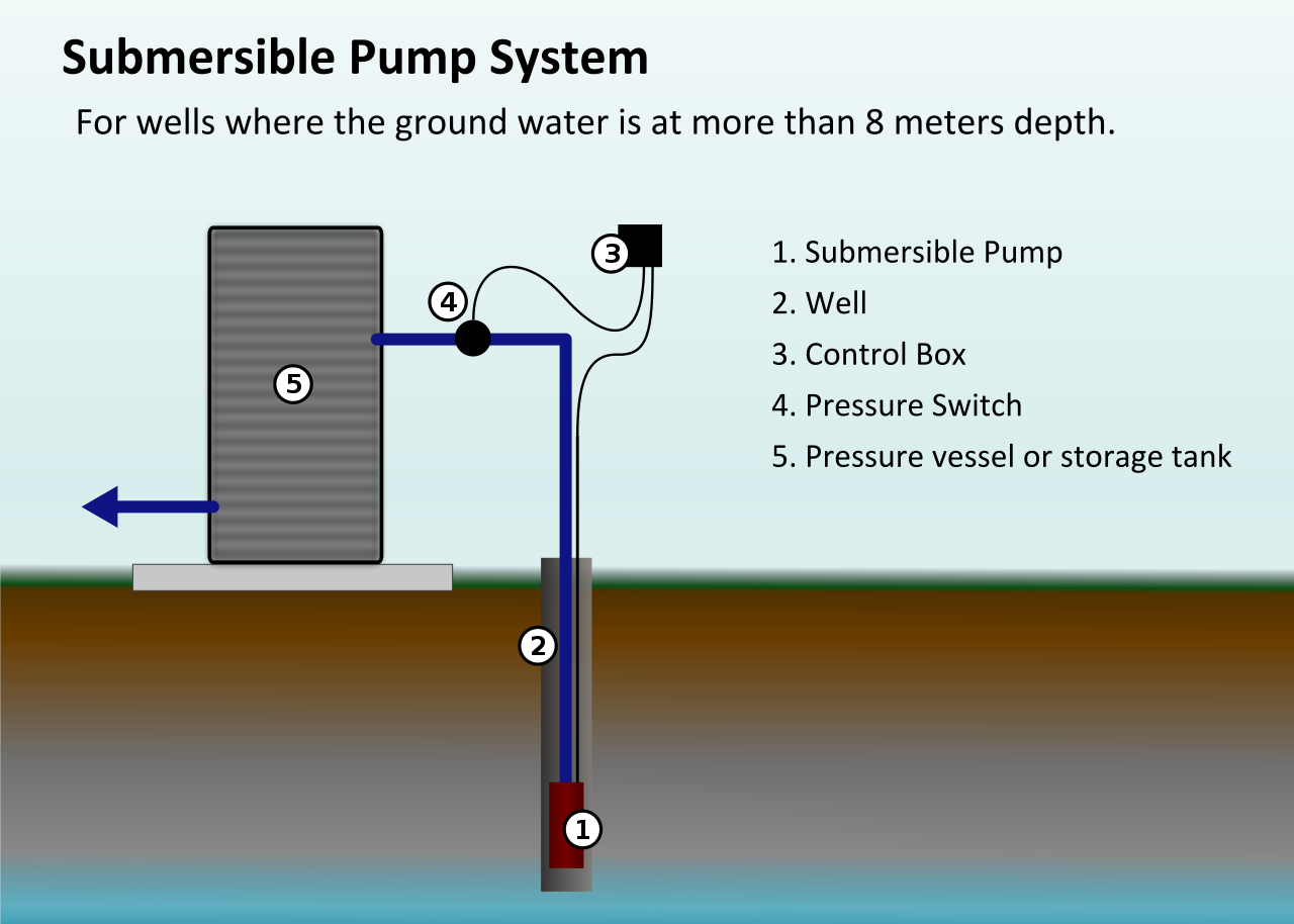
Pressure Switch
Submersible pumps use pressure switches to control their operations due to a built-in diaphragm that moves back and forth as a result of a water system’s pressure. Various types of pressure switches are available to handle a wide range of pressure ratings and electrical currents.
Pressure Gauge
Pump pressure gauges allow you to monitor the pump’s operation easily. Your pump switch is also visible by the pressure gauge, which indicates whether it is ON or OFF. Located above the T-head of the water tank, these gauges are located in the accessory parts.
Relief Valves
In the case of a pressure switch malfunction, the relief valve protects the plumbing system from excessive pressure and allows the system to build pressure beyond the predetermined pressure. Water damage can occur if the plumbing components and pipes are subjected to extreme pressure.
Drain Valves
Drain valves are located on the second outward-facing accessory port. In the case of pressure tanks that need to be replaced, drain valves can facilitate taking water samples, acquiring water from systems, and allowing access to drain the tank and water system. A drain valve is also known as a sediment faucet or boiler drain valve.
Ball Valves
The plumbing system should be isolated from the water well pressure system by installing a ball valve on the discharge side of the pressure tank. The ball valve can be used to shut off the house’s water supply if a major component of the plumbing system fails.
Sediment Filter
The sediment filter is responsible for filtering your water. This prevents sediment from entering water treatment equipment, such as softeners and hot water heaters. Water treatment equipment that does not contain sediment is more efficient and will last longer.
Considerations in Selecting Parts of Submersible Pump
It is best to treat the submersible pumping system as a whole rather than individual components:
- Choosing the right pump size and type will be dependent on the productivity and well fluid properties.
- A wellbore configuration and fluid properties will determine the type of intake.
- A pump’s horsepower and wellbore configuration will dictate the choice of seals and motors.
- When selecting tubing size and type, it is important to consider the production rate and wellbore configuration.
- The diameter and type of cable will be determined by electrical requirements, wellbore configurations, chemical injection protocols, and fluid properties.
- Selecting a wellhead is determined by the size of the tubing, casing, and cable, as well as pressure and environmental restrictions.
- Depending on the electrical requirements and well control requirements, a motor starter and controller must be chosen.
- The transformers that are needed depend on the electrical requirements and the type of motor starter that is chosen.
Download PDF for Parts of Submersible Pump
For your convenience, a PDF version of this document is available for download, allowing you to access it whenever you need it. Please click the following links to get started.
Buy Equipment or Ask for a Service
By using Linquip RFQ Service, you can expect to receive quotations from various suppliers across multiple industries and regions.
Click Here to Request a Quotation From Suppliers and Service Providers
Read More on Linquip
- Submersible Pump: Working Principles, Function & Diagram
- Types of Submersible Pumps: All Classification With Details
- 10 Parts of Reciprocating Pumps + Function, Application and Working
- Parts of Water Pump
- Parts of Centrifugal Pumps
- 12 Parts of Sump Pump + Diagram
- 6 Parts of Pool Pump + Diagram & PDF
- Diaphragm Pump Parts List + Function & Application
- 7 Parts of Gear Pump and Function + Diagram & Applications
- 8 main Parts of Piston Pump and Function + Work & PDF
- Top Dosing Pump Manufacturers and Suppliers in 2022
- Top Water Pump Manufacturers and Suppliers in 2022
- The 7 Best RV Water Pump In 2022 (Clear Guide + Review)
- The 10 Best Electric Air Pump in 2022 (Clear Guide)
- The Best HVAC Vacuum Pump in 2022 (Clear Guide)
- 9 Different Types of Rotary Pumps + PDF
- The 5 Best Well Pump in 2022 (Clear Guide)
- The 10 Best Condensate Pumps of 2022: A Complete Guide
- 13 Parts of Concrete Pump with Name & PDF
- 5 Types of Concrete Pumps + PDF
- 7 Parts of Screw Pump: Advantages and Disadvantages
- 10 Parts of Hydraulic Pump + PDF & Function
- Parts of Oil Pump
- Types of Centrifugal Pumps: All Classification & Working Principles
- Centrifugal Pump Working Principle with Diagram
- Delving Deep into Submersible Well Pumps: How Do They Work?



I find difficult to download the PDF of Submersible pump
Thanks for visiting our website, Muhammad! We first apologize for any inconvenience experience you had with this article. Your valuable comment will be considered for the next update of the post.
Hello sir,
I need information regarding submersible motors/pumps components. What is the standard components and Non standard Components of submersible motors.