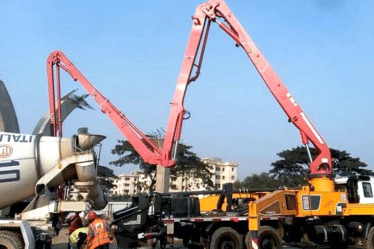
Essential parts of concrete pump allow the machine to transfer liquid concrete from one place to another. Concrete pumps have the advantage of enabling the placement of concrete at a faster rate even in areas with limited access. In today’s construction activities, concrete needs to be placed in hard-to-reach areas, so concrete pumps are used. As ready-mixed concrete has grown throughout the world, pumping needs have grown dramatically. Among the most efficient and cost-effective pieces of equipment for placing concrete that we have today is the Concrete pump.
Linquip’s website offers a wealth of information on concrete pumps. If you have any questions regarding any of the equipment applied in the construction industry, our experts are on hand to assist you. An excellent place to begin learning about pumps is Linquip’s article titled “Pump: Working Principles, Function & Diagram.“
Have you seen how a concrete pump works so far? We have a wide selection of Concrete Pump Products and associated components to meet your needs. What type of concrete pump is your business currently in need of? All Concrete Pump Devices for Sale are accessible for free online at Linquip. Linquip gives you the opportunity to ask all Concrete Pump Suppliers and Companies to provide you with a free quote/information regarding concrete pump prices.
There are diverse types of concrete pumps that can be used for a variety of construction projects. Concrete pumps must be both efficient and economical during construction projects. In addition, they should be specifically designed for the project.
Let’s begin today’s post by explaining a little about concrete pumps, their types, and their operation. Next, we’ll consider concrete pumps in more detail.
⇒ View a List of Pumps for Sale and Their Suppliers ⇐
An Introduction to Concrete Pumps
The construction industry is booming, and its demand is expected to rise in the future. Approximately 200,000 people a day are moving into urban areas around the world, and all of those new residents need housing, medical services, schools, transportation infrastructure, etc. Construction contractors and laborers will almost certainly be in high demand in the coming years due to the construction of urban infrastructure to meet growing population needs.
In the construction business, reliability and efficiency are of the utmost importance. However, complex, large projects are especially susceptible to falling behind schedule. According to investigations, an enormous 98% of large-scale construction projects experience delays or cost overruns. On average, a large-scale construction project runs 20 months behind schedule – almost two years.
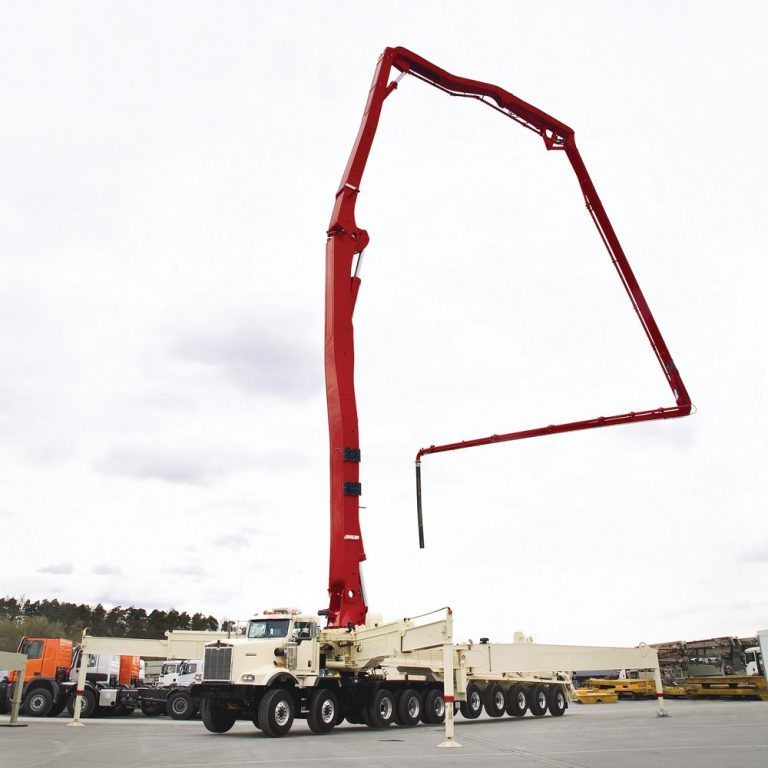
It is crucial to use the best, most efficient equipment in order to prevent issues like these. With regard to pouring concrete, concrete pumps offer considerable advantages in terms of efficiency and ease of use.
Before the early 20th century, concrete was usually mixed on-site and transported to the formwork via wheelbarrows or buckets lifted by cranes. This process took a lot of time and labor. Concrete was first pumped through pipes in 1927 by German engineers Max Giese and Fritz Hull. During the pour, concrete was pumped up to a height of 38 meters (125 feet) and a distance of 120 meters (130 yards). Soon afterward, Jacob Cornelius Kweimn patented a concrete pump in Holland.
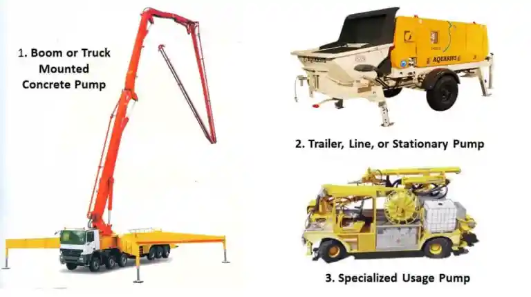
In the construction industry, a concrete pump is a machine that transfers liquid concrete via pumping. Concrete pumps come in two varieties.
Boom Pumps
A truck-mounted concrete pump or a semi-trailer-mounted unit is the first type of pump. In order to accurately place concrete, it is used with a robotic arm that is controlled remotely by remote control. These pumps are referred to as boom pumps. On a large construction site, you are most likely to see boom pumps being used since such pumps are capable of pumping huge volumes, and placing booms are relatively labor-saving devices. Concrete boom pumps have proven to be a good alternative to line-concrete pumps.
Line Pumps
Generally, the second type of concrete pump is mounted either on a truck or on a trailer, and it’s referred to as a line pump or trailer-mounted concrete pump. Manual attachment of steel or flexible concrete placing hoses is required for this pump. Concrete is placed by connecting those hoses and routing them to the appropriate places. Hoses typically have a length of 10′, 12.5′, 25′, and 50′, depending on their diameter. Line pumps usually pump smaller volumes of concrete compared with boom pumps and are used for the placement of smaller volumes of concrete, for example, in swimming pools, sidewalks, and single-family homes.
The following are some examples of line pumps:
- Stationary pumps: The most basic type of concrete pump is the stationary pump or trailer-mounted pump. These pumps are mounted on small trailers. Towing a stationary pump to a job site requires a separate truck. In addition, stationary pumps lack booms, so separate pipelines or placing hoses are required to transport concrete from the pump to its destination. Additionally, a separate boom is needed for the precise placement of concrete.
- Truck-mounted static pump: These pumps are mounted to truck beds so workers can drive them directly to the job site. Because these types of trucks do not come with placing booms, they will need to use individual placing hoses to place the concrete where it needs to go.
- Truck mixer pump: The all-in-one concrete mixer is equipped with a pump, making it possible to pump directly from the mixer. While this model works well in many applications, it does require a job site setup that allows one to drive a large mixing truck right up next to the concrete pour point.
Other types of concrete pumps are skid mounted and rail-mounted, but these are uncommon and typically used only on specialized job sites like mines and tunnels.
Working Principle of Concrete Pump
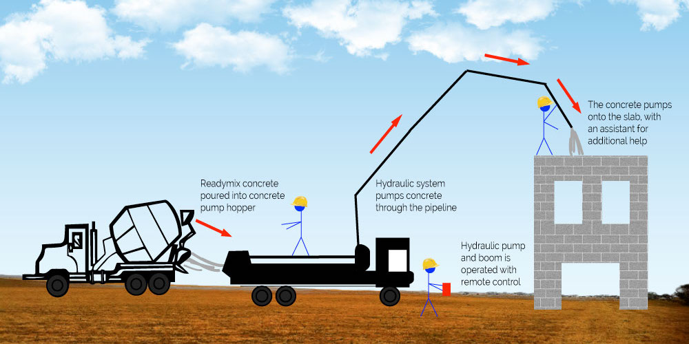
Concrete pumps transport liquid concrete from the location where it is mixed to the location where it is needed on a construction site. The valve system and hydraulics are used to operate the pumps.
Concrete is first mixed within the rotating drum of a mixing truck when concrete is needed. Concrete is then poured from the truck into a hopper, which keeps mixing the concrete so it won’t solidify. By means of a valve system, the concrete pump sucks the liquid concrete from the hopper and delivers it into the appropriate area for laying down, sometimes using auxiliary hoses.
Internally, a twin-cylinder hydraulic concrete pump has two parallel cylinders. Within the cylinders are drive pistons that move them back and forth in opposite directions. One goes forward, the other backward.
Concrete is pulled out of the hopper by the first cylinder, also known as the material cylinder. Concrete is discharged out of the pump using the second cylinder, the discharge cylinder. In a tandem function, the pistons alternately pull in and push out their respective volumes of liquid concrete. A continuous flow of concrete creates hydraulic pressure in the cylinders, which causes them to alternate back and forth. Maintaining a continuous flow is also necessary to prevent solidified concrete.
A skilled concrete pump operator controls a concrete pump. By directing the boom or hose, the pump operator controls the pump’s operation, position, and output. In addition to driving the pump to the job site, the operator has to set it up, clean it after use, and make any necessary repairs.
Design of a Concrete Pump
During the design phase, engineers faced many challenges in developing an efficient concrete pump. A key challenge was concrete’s viscosity, abrasiveness, and weight and the fact that it solidifies quickly when it is not in motion. Concrete pumps are most often piston-style pumps, as piston pumps are able to produce enough pressure to move concrete.
Components of Concrete Pump
Three hydraulic circuits operate the concrete pump, and although they are integrated, each is designed to serve a particular function within its operation. Here are the three circuits:
Concrete Pump Parts name are:
- Main Pump Circuit
- S-Tube Shift Circuit
- Auxiliary Circuit
- Elbow with Wear Detecting Holes
- Outrigger
- U-Shaped Bottom of the Hopper
- Power Operated Vacuum Pump
- Spraying Arm
- Air Compressor
- Additive Pump
- Control Panel
- Remote Control
- Motorized Chassis
Main Pump Circuit
This circuit controls the hydraulic drive cylinders.
Piston Pump
A variable displacement axial piston pump with a swashplate design powers the main hydraulic pump. There are pistons that travel along the tiltable swashplate. Changing the angle of the swashplate changes the stroke length of the pistons, which subsequently varies fluid displacement. More flow is generated when the swashplate has a larger angle. By using the volume control combined with the load sense feature, the swashplate angle can be adjusted.
Motor
An engine or electric motor drives the main hydraulic pump. During normal operation of the engine, the pump switch is in the OFF position, the VOLUME control is minimized, and the engine is running; no demand is placed on the pump. In this case, the pump is de-stroked, which means that it is only producing a minimal amount of flow to allow the pump to be lubricated. Whether the engine is idling or running at maximum RPM, this lubrication occurs.
Valve Manifold
A manifold is installed on the main pump circuit to accommodate the relief valve, the check valve, the flow control, and the pilot-operated directional valve. The cycle valve is an electrohydraulic solenoid-operated directional spool valve. A hydraulic drive cylinder directs oil from a main hydraulic pump to one or more cylinders.
Throttle Control
The pump circuit is energized by setting the engine speed at maximum RPM using the throttle control. VOLUME can be adjusted anywhere between zero and FULL. By doing so, the load sense detects the demand and activates the pump. As the volume control is opened, the pump will now produce the flow accordingly. With the PUMP switch OFF, the flow from the hydraulic pump passes through the main directional valve, then returns to the hydraulic tank.
Cycling Circuit
When the PUMP switch is ON, the cycling circuit is activated. This generates an electrical signal that activates the coils of the main directional pilot valve, as well as activating the S-Tube directional valve.
Material Cylinders
Two material cylinders alternately pump the material, resulting in material pumping action. Alternating cycling is triggered by electrical signals generated by proximity sensors positioned in the flush boxes positioned along the suction and retraction strokes of each material cylinder.
With the piston coupler passing under the proximity sensor, an electrical signal is generated that is conveyed to the logic controller for alternating the action of the material cylinders and synchronizing the motion of the S-Tubes. A logic controller provides an output signal that energizes the coils of the main directional pilot valve as well as the S-Tube directional valve.
Relief Valve
A relief valve has been installed to protect the main pump circuit from excessive pressure. Consequently, when the pressure in the system reaches the maximum factory setting, the relief valve opens, letting the oil return to the tank.

S-Tube Shift Circuit
This circuit controls the operation of shifting the s-tube between the material cylinders.
There is only one outlet for pumping material, so a means must be provided for transferring the material from the cylinder to the outlet and then into the delivery line. The hopper is equipped with an S-tube to accomplish this task. There are two material cylinders and one s-tube, so the s-tube must be shifted from one cylinder to another, depending on which is loaded with pumping material.
S-tube shift hydraulic circuits have an open center, which means that when the control valves are in neutral, the internal passages of the valves are open, permitting hydraulic fluid to return to the tank. Engine running causes the hydraulic pump to pump oil, which, without any control energized, will flow back to the tank through the shift circuit.
Tandem Pump
A tandem pump is used in one section of the shift circuit to meet the flow and pressure requirements. Alternatively, a single pump can be used if no auxiliary equipment is required. A tandem hydraulic pump has a gear pump design with a fixed displacement, meaning it produces the same displacement continuously at a pre-set maximum according to engine rotational speed. It is connected directly to the main hydraulic pump and is therefore driven by it.
Manifold Block
Shift circuits are also equipped with manifold blocks, just like the main hydraulic circuit. There are three cartridges in this set: an unloader, a relief, and a solenoid valve.
The top of the block is a solenoid-operated directional valve, and the front of the block is an s-tube selector control valve.
Auxiliary Circuit
This circuit controls the operation of the agitator as well as other auxiliary equipment.
As part of the unit’s auxiliary circuit, the hydraulic function of the agitator has been designed and installed. The agitator rotates so that the material in the hopper will be mixed and the concrete cylinders fed.
Similar to the s-tube shift circuit, the auxiliary circuit is served by the second stage or section of the tandem pump employed on the main circuit. While the engine is running and the throttle is set to maximum RPM, the flow from the tandem pump is fed to a single spool directional control valve. Also utilized in this circuit is a solenoid valve cartridge or dump valve that is designed as a safety valve to prevent flow to the auxiliary circuit when the emergency stop circuit is activated.
When the engine is started, the normally open cartridge transfers oil from the tandem pump to the tank, thus preventing the operation of the auxiliary circuit. As soon as the emergency stop circuit is reset, an electrical signal is generated to activate the solenoid, stopping the flow directly back to the tank by closing the cartridge. Instead, the flow is directed to the single-spool directional control valve for operation. The valve incorporates a relief cartridge to prevent excessive pressure.
With the lever pushed, the agitator will turn in a forward direction as hydraulic fluid is directed to the motor on that side. Reversing the rotation is accomplished by turning the lever in the opposite direction.
In concrete pump vehicles, a significant function is to pump mixed concrete high up in the air and over long distances using the pumping tube installed inside the cylindrical drum. The main parts of a stationary concrete pump include:
Elbow with Wear Detecting Holes
Wear-detecting holes in concrete pump elbows, made from quench casting material, optimize durability, increase safety, and smooth the flow of ready mixed concrete.
Outrigger
An obliquely overhanging outrigger has larger stable moment areas by widening the overhanging area.
U-Shaped Bottom of the Hopper
The U-shaped bottom hopper facilitates the introduction of ready mixed concrete into the intake port. The efficient inflow of ready mixed concrete reduces the remaining volume, making cleaning easier.
Power Operated Vacuum Pump
It is equipped with a battery-powered vacuum pump. Once the inner drum has been vacuumed, the vacuum pump is automatically turned off.
In order to ensure homogeneous application of sprayed concrete, the pump design is aimed at minimizing pulsations and discontinuities in concrete flow. Thus, the required quality and layer thickness are met, and there is less rebound (concrete that doesn’t remain on the wall).
Spraying Arm
In the mechanized equipment, the spraying arm positions the concrete flow at the required spot. Since spraying for distances up to 17 m can be reached, telescopic elevation platforms or scaffolding are not required.
Several materials are mixed within the spraying head to be applied using the nozzle, including concrete, accelerators and air. The design and dimensions of the nozzle are crucial to ensuring the concrete is compressed correctly and minimizing rebound.
Air Compressor
By using the air compressor, the concrete mixture is given the kinetic energy it needs to be sprayed and compacted. Ideally, shotcrete should be able to impact the surface with a certain velocity, and this can only be achieved by the compressor’s air flow combined with the right nozzle diameter. For example, the airflow of 12 m3/min with a 65 mm nozzle diameter does not produce enough kinetic energy. Using a nozzle of 35-40 mm produces the same result, provided the spray distance is kept at 1-2 meters.
Additive Pump
Accelerators are used to speed up the hardening of the concrete in order to achieve the required early strength development. A synchronized dosing device and concrete pump ensure that the dosage is based on concrete flow at all times.

Control Panel
The control panel is positioned for easy operation and to confirm the ready mixed concrete condition inside the hopper. Operators and pumping equipment can work in a unified manner when switching operations are performed. The switch controls the pumping speed (high speed / low speed) based on its operation. Additionally, a digital display indicates when to replace the pumping tube and perform maintenance checks on the discharging volume meter.
Remote Control
An operator can control the concrete spraying process on-site using the remote control. All the concrete components (concrete, additives, etc.) and the equipment components (spraying arm, nozzle) are controlled via the remote control. Remote controls are available either wirelessly or via cable, allowing the operator to work from anywhere.
Motorized Chassis
Motorized chassis is used to drive the equipment to the spraying zone. Dimensions, directions, and turning radius are crucial in spaces with limited space. In order to reach areas with slopes and irregular terrain, motorization, angles of attack, and climbing ability are crucial.
Common Use of Concrete Pumps
Among the many construction applications for concrete pumps are:
- Slab building foundations: Buildings without basements have flat slabs for their foundations. Solid foundations that aren’t prone to letting in water and sagging are essential. Concrete pumps are vital to ensuring the concrete is delivered where it needs to be quickly and efficiently. By doing so, any imperfections in the foundation will be avoided.
- Building foundations with basements: Constructing a foundation for a building with a basement is a little more complicated. It is crucial to have concrete pumps such as boom pumps so there are no delays that can cause errors or harden parts of the concrete before they are ready. A boom pump for basement foundations contributes to the timely completion of the building project.
- High-rise buildings: boom pumps are often required due to the high elevation and long reach they provide. Boom lifts can help construction companies pump concrete to upper floors quickly, efficiently, and safely, keeping the project on schedule.
- Highway overpasses and tunnels: To support the daily traffic that passes over highway overpasses, they must be made of durable concrete. Tunnels under highways also must be able to withstand the weight of the earth above them without collapsing. Making use of a concrete pump ensures the job gets done effectively. Concrete pumps also come in handy in overpasses and tunnels because they allow you to work with some elevation, and a boom pump is particularly useful because it provides additional lift.
- Bridges and dams: Dams and bridges must be large, strong, and steady to withstand the weight of heavy vehicles and the effects of high water pressure. For example, boom pumps are able to pump concrete rapidly to the top of tall bridges and dams due to their lift and extension.
- Parking structures: Parking garages usually include several levels, and without a concrete pump, concrete can’t reach the upper levels. Construction of a tall parking structure can be completed quickly and without wasting labor by using a concrete pump.
- Sidewalks and driveways: When constructing a new home, many homeowners are most concerned with the house itself. However, sidewalks and driveways play an equally important role. It’s tempting for some homeowners to pour their own driveways and sidewalks, but if you’d like a smooth, stable, and properly cured driveway or sidewalk, you’ll have to engage a professional company that’s able to provide a boom pump.
- In-ground swimming pools: An in-ground pool is built on a concrete foundation, just like a basement. Concrete pumps, in particular boom pumps, are an excellent choice for the construction of backyard swimming pools. Rather than driving a big truck through the backyard, a boom pump can conveniently reach over the house and pour concrete without destroying the yard.
- Patios and garden shed foundations: Concrete pumps such as boom pumps are ideally suited for foundations for patios and garden sheds. Concrete slabs for those features can easily be poured by boom pumps right in the backyard from the street.
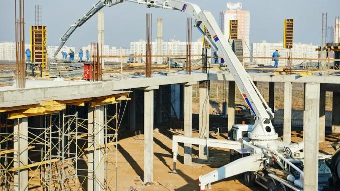
Choosing a Right Boom Concrete Pumps
The fundamental properties to evaluate when comparing boom concrete pumps include their height from the ground, pumping rates, horizontal reach, cylinder diameter, cylinder lengths, concrete pressures, maximum heads, and power requirements. Concrete pumps are priced differently depending on a range of factors, but generally speaking, the larger the boom and the higher the pumping rate, the more expensive the system will be.
Businesses in the construction industry are generally able to obtain portable concrete mixers with pumps at the lowest prices by approaching overseas manufacturers. Numerous companies operate internationally that export concrete pumps internationally, so businesses don’t need to worry about shipping and import themselves. The most important thing to remember, however, when looking at boom concrete pumps from international suppliers is to see if the pump specifications are listed in imperial or metric units.
Is There a Maximum Length for Pumping Concrete?
The typical range of a line pump is 150 meters, along with flexible piping options. When fully extended, boom pumps can reach 72 meters – and additional extensions are also available.
What Are the Benefits of Concrete Pumps?
Some of the advantages of using concrete pumps in a construction project include:
- Faster pouring of concrete.
- Fewer laborers required.
- Higher quality and accuracy of concrete pouring.
- Increased concrete strength.
- Convenient pouring method.
Do Concrete Pumps Have Any Disadvantages?
The use of pumping concrete is not suitable whenever the distance is too long, and the height is too high. For pumped concrete to be transported, the concrete must have a pumpability, which will raise the water-cement ratio of the concrete. Shrinkage and cracking are common problems with such concrete.
Download Parts of Concrete Pump PDF
We included the option to download the PDF version of this document so you can have access to it. You can get started by clicking the link below.
Buy Equipment or Ask for a Service
By using Linquip RFQ Service, you can expect to receive quotations from various suppliers across multiple industries and regions.
Click Here to Request a Quotation From Suppliers and Service Providers
Read More on Linquip
- 5 Types of Concrete Pumps + PDF
- 20 Parts of Submersible Pump + PDF
- 10 Parts of Reciprocating Pumps + Function, Application and Working
- Parts of Water Pump
- Parts of Centrifugal Pumps
- 12 Parts of Sump Pump + Diagram
- Diaphragm Pump Parts List + Function & Application
- 7 Parts of Gear Pump and Function + Diagram & Applications
- 8 main Parts of Piston Pump and Function + Work & PDF
- The 5 Best Well Pump in 2022 (Clear Guide)
- The 10 Best Condensate Pumps of 2022: A Complete Guide
- Best Check Valve for Sump Pump: 9 of the Best Models
- The 8 Best Water Pumps of 2022 with Pros. and Cons
- The 5 Best Air Source Heat pump in 2022 (Clear Guide)
- The 10 Best Electric Air Pump in 2022 (Clear Guide)
- The Best HVAC Vacuum Pump in 2022 (Clear Guide)
- Types of Water Pumps and Their Principles
- 6 Type of Sump Pump and Which Are Better to Buy?
- Types of Pump Casings (In Centrifugal Pumps & Others) + Pros & Cons
- 3 Types of Positive Displacement Pump + Name & PDF
- 5 Types of Vacuum Pump and Applications + PDF
- 3 Types of Well Pumps + Applications
- 3 Types of Oil Pumps + Working Principle & PDF
- 6 Main Types of Dynamic Pumps: Examples + PDF
- 5 Main Types of Fuel Pump & How They Works?
- 3 Types of Vane Pumps: Working Principles & Application
- Types of Piston Pumps
- Types of Fire Hydrant Systems

